If you have searched for a "conformal cooling PDF" or "conformal cooling PPT" to get a single, complete overview of this technology, you have likely found fragmented vendor brochures, narrow academic papers, or outdated slide decks that each cover only one angle. This guide consolidates every major aspect of conformal cooling into one continuously updated reference — from the fundamental physics to design rules, manufacturing methods, simulation workflows, cost models, ROI calculations, and industry-specific applications.
Bookmark this page. It is the only conformal cooling resource you will need.
1. What Is Conformal Cooling?
Conformal cooling is a mold temperature management strategy in which cooling channels follow the contour of the part surface rather than being constrained to straight-line drilled holes. By conforming to the part geometry, these channels maintain a nearly uniform distance from the mold cavity surface everywhere, eliminating the hot spots and cold spots that plague conventional cooling circuits.
The result is faster, more uniform heat extraction. Cycle times drop 20 to 40 percent. Warpage and sink marks decrease dramatically. Scrap rates fall by 50 to 80 percent. And part dimensional consistency improves to the point where previously borderline molds begin producing reliably within tolerance.
Conformal cooling channels are made possible by additive manufacturing — specifically metal 3D printing processes such as Selective Laser Melting (SLM) and Direct Metal Laser Sintering (DMLS) — which can produce internal channel geometries that are impossible to machine with conventional drilling, milling, or EDM.
2. The Physics of Cooling: Heat Transfer Fundamentals
Understanding why conformal cooling works requires understanding the heat transfer equation that governs mold cooling. The rate of heat removal from the mold surface is determined by three mechanisms: conduction through the steel, convection from the channel wall to the coolant, and the coolant's ability to carry that heat away.
Conformal cooling improves every variable in this equation. By running channels closer to the cavity surface, the conduction path through the steel is shorter and more uniform, keeping the channel wall temperature (and therefore ΔT) consistently high. By following the part contour, total effective cooling surface area (A) increases. And by enabling optimized channel cross-sections, turbulent flow is maintained throughout the circuit, maximizing the convective coefficient (h).
The critical metric is mold surface temperature uniformity. Conventional cooling typically produces temperature variations of 15 to 30 degrees C across the cavity surface. Conformal cooling reduces this to 3 to 5 degrees C — a 5x to 10x improvement that directly translates to reduced warpage, fewer sink marks, and more consistent crystallinity in semi-crystalline resins.
The key insight: reducing the wall distance d from 25 mm (typical for gun-drilled channels) to 8 to 12 mm (typical for conformal channels) increases heat flux by 2x to 3x. This is the primary mechanism behind cycle time reduction.
The Conformal Cooling Process: Step-by-Step Thermal Management Read more →3. Design Rules Summary: D / P / W
Three parameters define the starting point for every conformal cooling channel layout. These are referred to as the D/P/W rules:
| Parameter | Definition | Recommended Range | Rationale |
|---|---|---|---|
| D (Diameter) | Internal channel diameter | 4–8 mm | Below 4 mm: excessive pressure drop. Above 8 mm: structural risk and uneven cooling. |
| P (Pitch) | Center-to-center spacing between adjacent channels | 2D to 3D | Closer spacing gives more uniform cooling. Below 2D: structural weakness. Above 3D: hot spots between channels. |
| W (Wall distance) | Distance from channel center to mold cavity surface | 1.5D to 2D | Closer = faster cooling, but below 1.5D risks mold deformation under injection pressure. |
D = 6 mm → P = 12 to 18 mm → W = 9 to 12 mm
For a PP container lid with 2.0 mm wall thickness, use D = 6 mm, P = 14 mm, W = 10 mm as the initial layout. Validate with thermal simulation before finalizing.
These rules are starting points, not absolutes. Our in-depth channel design guide covers advanced scenarios. Part geometry, resin type, cycle time targets, and injection pressure all influence the final design. Areas with thick ribs or bosses may require locally tighter pitch. Thin-wall regions may allow smaller channels closer to the surface.
Conformal Cooling Channel Design: Complete D/P/W Guide with Worked Examples Read more → Conformal Cooling Design: From CAD to Production-Ready Insert Read more →4. Channel Geometry Types
The geometry of the cooling channel — its path through the mold insert — is as important as the D/P/W parameters. Four primary channel routing strategies are used in production conformal cooling:
Channels run in parallel passes back and forth across the insert. Best for flat parts like lids, panels, and plaques. Low pressure drop. Limited effectiveness on complex 3D geometries because the channels cannot closely follow curved surfaces.
Channels wrap around cylindrical cores or cavities in a helix pattern, maintaining constant wall distance around the entire circumference. Standard for bottle preform molds, round container lids, and cylindrical electrical connectors. Provides the most uniform cooling on round parts.
Channels follow the exact 3D contour of the part cavity, maintaining constant wall distance regardless of surface curvature. This is the "true" conformal approach and provides the best thermal uniformity on complex geometries like automotive interior trim, medical device housings, and consumer electronics enclosures.
TPMS structures such as gyroid, Schwarz-P, and diamond lattices create interconnected cooling networks with extremely high surface area-to-volume ratios. Heat transfer rates can be 2 to 4 times higher than conventional round channels. Currently used in high-performance applications where maximum cooling rate justifies the additional design complexity. Requires specialized simulation tools and careful pressure-drop management.
5. Materials for Conformal Cooling Inserts
The choice of insert material depends on the resin being molded, required tool life, thermal conductivity needs, and budget. The three most common materials for 3D-printed conformal cooling inserts are:
| Material | Hardness (HRC) | Thermal Conductivity | Best For | Relative Cost |
|---|---|---|---|---|
| Maraging Steel (MS1 / 18Ni300) | 50–54 | 20 W/m·K | High-volume production, abrasive resins (GF-filled), long tool life | $$ |
| Tool Steel (H13 / 1.2344) | 46–52 | 24 W/m·K | Hot work applications, die casting, high-temperature resins | $$ |
| CuCrZr (Copper Alloy) | 28–35 | 320 W/m·K | Maximum cooling rate, thin-wall packaging, blow molds | $$$ |
Maraging steel is the workhorse material for injection molding conformal cooling inserts — it offers excellent hardness after age hardening, good machinability for post-processing, and proven performance across millions of shots. CuCrZr copper alloy is used when thermal performance is the primary driver and wear resistance is less critical (e.g., blow molds, packaging molds running non-abrasive resins).
Conformal Cooling Materials: MS1, H13, CuCrZr — Full Comparison with Selection Guide Read more →6. Manufacturing Methods
Conformal cooling inserts are produced using two primary manufacturing approaches, each with distinct strengths:
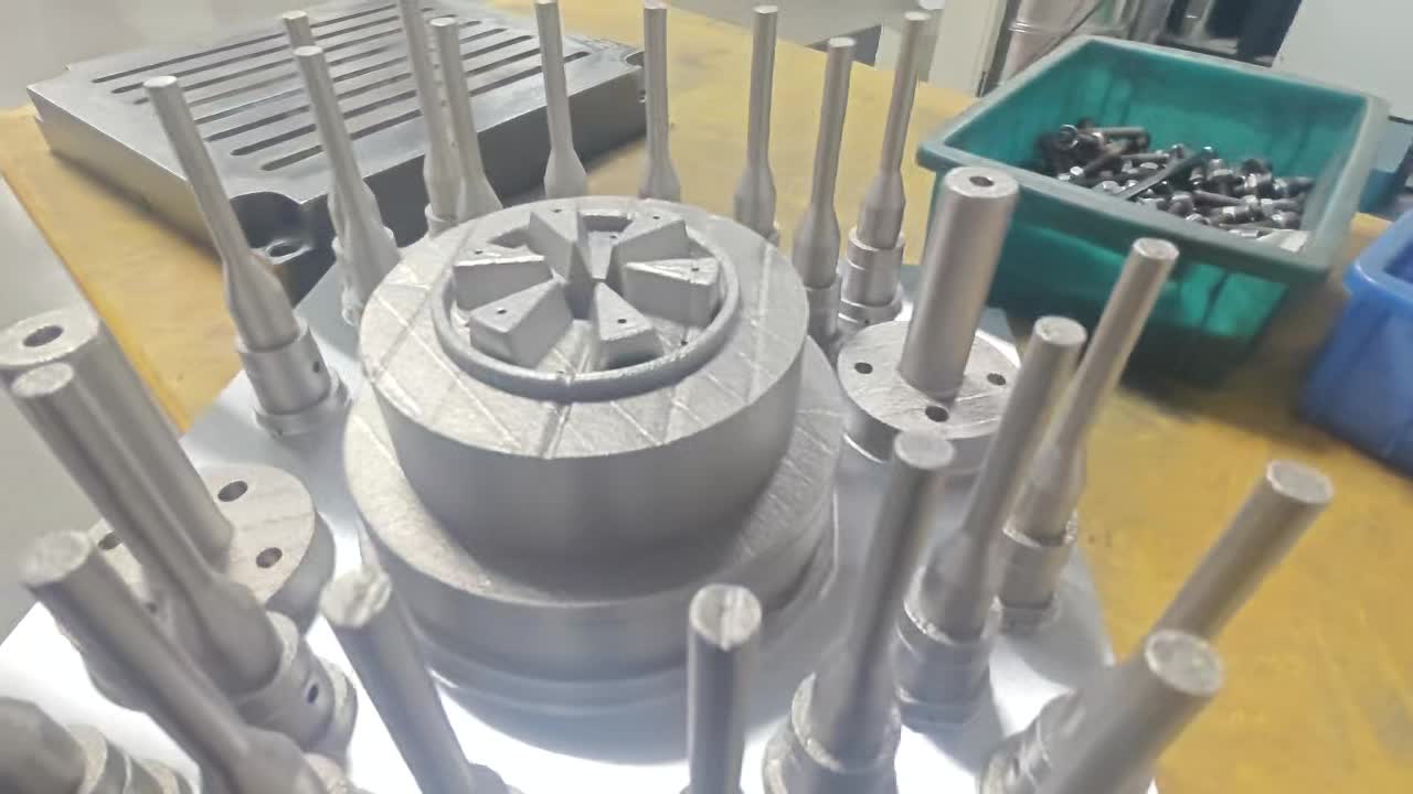
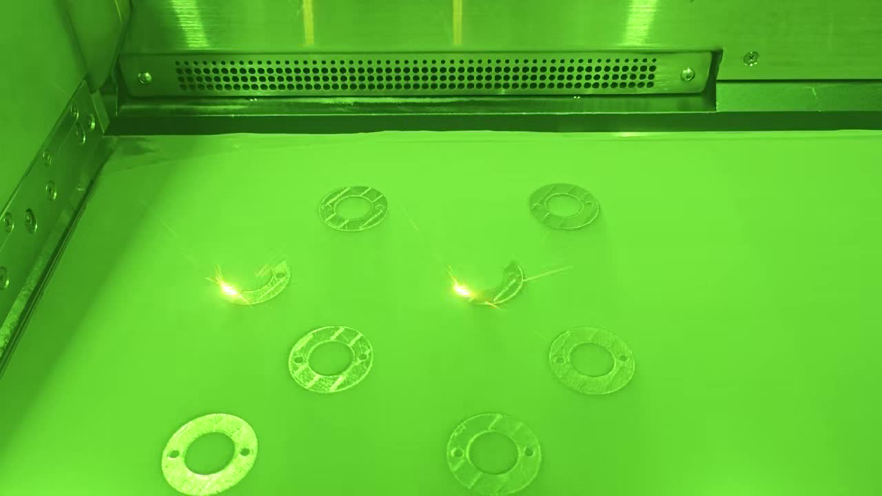
Laser Powder Bed Fusion (LPBF / SLM / DMLS)
Metal 3D printing builds the insert layer by layer from metal powder using a high-power laser (200–400W). This is the most common method for conformal cooling inserts. It can produce channels as small as 3 mm diameter with complex 3D routing, internal lattice structures, and TPMS geometries. Typical layer thickness is 30 to 50 microns, producing density above 99.5%. Post-processing includes stress relief heat treatment, CNC machining of mating surfaces, and surface finishing.
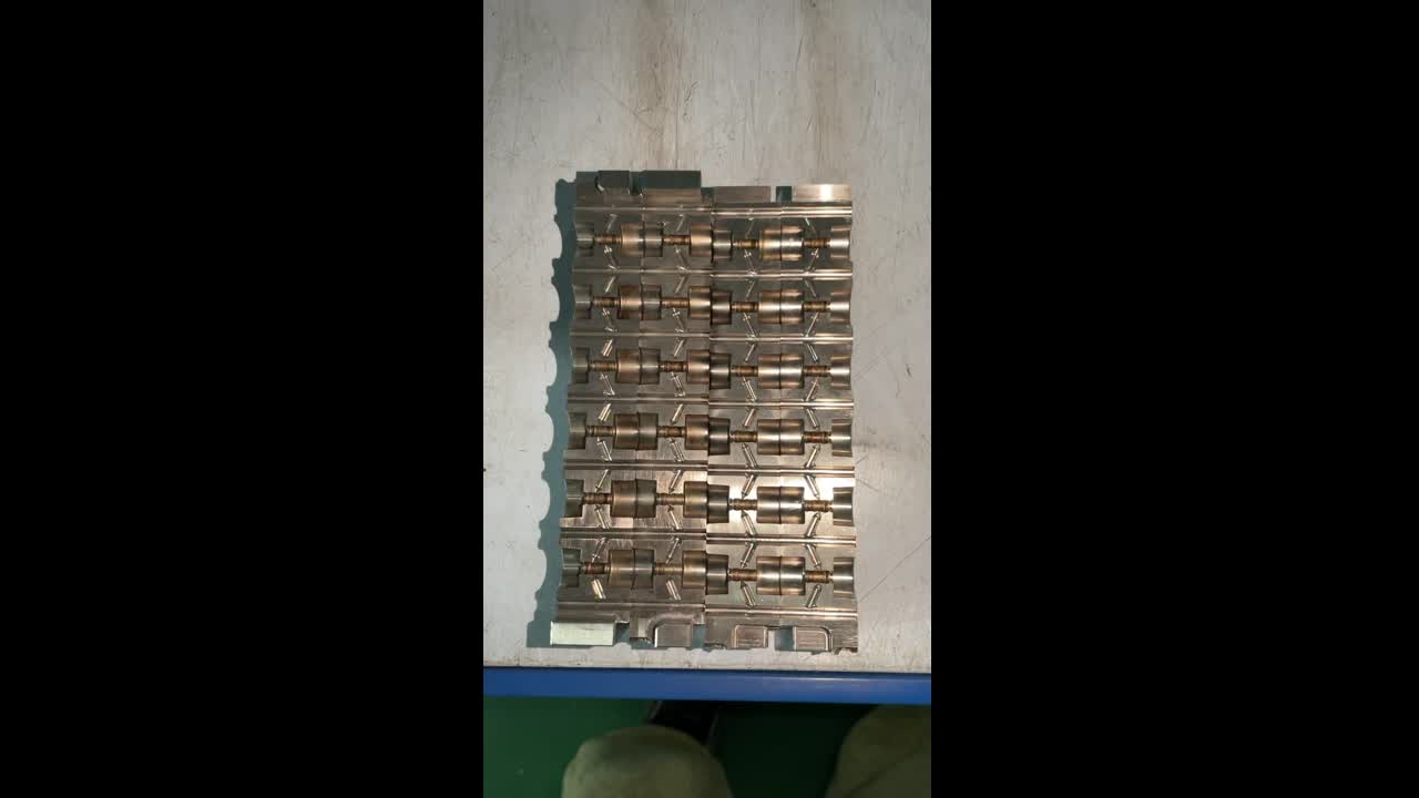
Vacuum Brazing (Hybrid Method)
For very large inserts where the build volume of available SLM machines is a constraint, or where cost optimization is critical, vacuum brazing offers an alternative. The insert is split into layers along strategic planes, channels are CNC-machined into each layer, and the layers are joined in a vacuum furnace. Bond strength exceeds 95% of parent material. This method is well-suited for inserts larger than 250 mm that would be impractical or uneconomical to 3D print.
Conformal Cooling & Additive Manufacturing: Process, Parameters, and Quality Control Read more → Conformal Cooling & 3D Printing: Technology Deep Dive Read more → SLM vs. DMLS for Conformal Cooling: Process Comparison Read more → Conformal Cooling by Vacuum Brazing: When and How to Use It Read more →7. Simulation Tools and Workflow
Simulation is essential for conformal cooling design. Unlike conventional straight-drilled channels where rules of thumb are often sufficient, conformal channels require thermal simulation to validate that the channel layout achieves uniform cooling without excessive pressure drop or structural compromise.
The standard simulation workflow follows four stages:
- Thermal Analysis: Model heat transfer from the melt through the mold steel to the coolant. Predict cavity surface temperature distribution and identify remaining hot spots.
- Flow Analysis: Simulate coolant flow through the channel network. Verify Reynolds number (turbulent flow requires Re > 4,000), pressure drop (target < 3 bar), and flow uniformity across parallel circuits.
- Structural Analysis: Verify that the insert can withstand injection pressure (typically 50–150 MPa) without deflection that would affect part dimensions or channel integrity.
- Cycle Optimization: Iterate channel layout, diameter, and pitch to minimize cycle time while meeting warpage and dimensional specifications.
| Software | Strength | Typical Use Case |
|---|---|---|
| Moldex3D | Dedicated mold cooling simulation, conformal channel library | Production conformal cooling projects |
| Autodesk Moldflow | Industry-standard fill + cool + warp, large user base | Full injection molding process simulation |
| SIGMASOFT | Virtual molding with multi-cycle thermal analysis | Thermal steady-state validation |
| ANSYS / COMSOL | General-purpose FEA, custom physics models | Research, TPMS lattice simulation |
8. Cost Overview
Conformal cooling inserts carry a premium over conventionally drilled inserts, but the cost structure is straightforward and the premium is typically recovered within weeks of production start.
Cost drivers include: insert volume (larger = more powder = higher cost), channel complexity (TPMS costs more than linear), material (CuCrZr costs approximately 2x maraging steel), post-processing requirements (tight-tolerance mating surfaces add CNC time), and quantity (repeat orders cost 15 to 25 percent less due to eliminated setup and programming time).
The critical insight: do not evaluate conformal cooling insert cost in isolation. The relevant metric is total cost of ownership across the production run, which includes the insert cost, the cycle time savings, the scrap reduction, and the quality improvement. On any run above approximately 50,000 shots per year, conformal cooling is almost always the lower total-cost option.
Conformal Cooling Cost: Detailed Breakdown, Price Drivers, and Budgeting Guide Read more →9. ROI Framework
The ROI of conformal cooling comes from four savings categories, each quantifiable from production data:
Annual throughput savings = (cycle time reduction %) × (annual shots) × (machine hour rate) × (original cycle time). A 30% cycle time reduction on a tool running 500,000 shots/year at $80/hr machine rate and 30-second original cycle saves approximately $100,000 per year.
Scrap savings = (scrap rate reduction) × (annual shots) × (part cost). Reducing scrap from 5% to 1% on 500,000 shots of a $3.50 part saves $70,000 per year in material and machine time.
Reduced warpage eliminates or reduces post-mold straightening, trimming, and inspection steps. Typical savings: $0.05 to $0.30 per part on operations that were previously required to bring warped parts into tolerance.
Shorter cycle times free machine capacity for additional production without capital expenditure on new presses. At $250,000 to $500,000 per press, the capacity value of a 30% cycle time reduction can be substantial.
Insert cost: $3,200 | Cycle time reduction: 28% | Annual shots: 800,000 | Machine rate: $85/hr | Original cycle: 25s
Throughput savings: ~$132,000/year | Scrap savings: ~$56,000/year | Total: ~$188,000/year
10. Application Guide by Industry
Conformal cooling delivers ROI across every industry that uses injection molding, die casting, or blow molding — but the specific benefits and design considerations vary by sector.
Highest volume, fastest payback. Cycle time reductions of 25 to 40% on door panels, instrument clusters, and PA66-GF30 structural brackets. IATF 16949 compatible with full documentation packages.
Dimensional precision required for FDA/MDR regulatory compliance. Conformal cooling eliminates the warpage that causes assembly failures on multi-component medical devices. Clean-room compatible processing.
Ultra-tight tolerances (often ±0.02 mm) on small, thin-wall parts. Conformal cooling provides the thermal uniformity required for consistent fill on micro-featured geometries.
Conformal cooling in die-casting molds extends die life by reducing thermal fatigue cracking and eliminates porosity caused by uneven solidification. Temperature uniformity is critical for surface quality on cosmetic castings.
11. Conformal vs. Conventional Cooling
The fundamental difference between conformal and conventional cooling is geometric freedom. Conventional cooling is constrained to straight-line drilled holes — the drill bit must enter and exit the mold block in a straight line. Conformal cooling channels can follow any path through the insert, maintaining optimal distance from the cavity surface regardless of part geometry.
| Attribute | Conventional Cooling | Conformal Cooling |
|---|---|---|
| Channel routing | Straight lines only | Any 3D path |
| Wall distance uniformity | Variable (10–40 mm) | Constant (8–12 mm) |
| Surface temp variation | 15–30°C | 3–5°C |
| Cycle time | Baseline | 20–40% faster |
| Scrap rate | Baseline | 50–80% lower |
| Insert cost | Lower upfront | 20–60% premium |
| Total cost of ownership | Higher (above ~50k shots/yr) | Lower |
12. Getting Started Checklist
Ready to evaluate conformal cooling for your next project? Follow this checklist to move from consideration to production-ready insert.
13. FAQ
Most conformal cooling PDFs and PPTs available online cover only one narrow aspect — a vendor slide deck, an academic paper, or a single case study. This guide consolidates every major topic into one continuously updated web resource. Bookmark this page instead of downloading static documents that become outdated.
The three foundational rules relate channel diameter (D), pitch (P), and wall distance (W). Start with D = 4 to 8 mm, P = 2D to 3D, and W = 1.5D to 2D. These ensure uniform heat extraction without compromising structural integrity. See Section 3 above for the full explanation and worked example.
A conformal cooling insert typically costs $1,500 to $6,000 — a premium of 20 to 60 percent over conventionally drilled inserts. However, payback is typically 1 to 12 weeks because cycle time reductions of 20 to 40 percent and scrap reductions of 50 to 80 percent generate savings that far exceed the upfront cost on runs above approximately 50,000 shots per year.
Automotive leads due to high volumes and strict tolerances. Medical devices benefit from dimensional precision for regulatory compliance. Consumer electronics benefit from cosmetic surface quality. Packaging benefits from extreme cycle-time sensitivity. Semiconductor and die-casting industries also see significant gains. See Section 10 for industry-specific details, or browse our conformal cooling case studies for real project data.
Leading tools include Moldex3D (dedicated cooling simulation), Autodesk Moldflow (industry-standard injection molding simulation), SIGMASOFT (virtual molding with thermal cycling), and ANSYS or COMSOL for custom FEA. MouldNova uses Moldex3D for production projects and validates against thermocouple data from actual production runs.
Complete Conformal Cooling Article Library
- What Is Conformal Cooling?
- Conformal Cooling Channels
- Conformal Cooling Channel Design
- Conformal Cooling Design
- Conformal Cooling Inserts
- Conformal Cooling Cores
- Conformal Cooling Mold
- Conformal Cooling in Injection Molding
- Conformal Cooling in Injection Moulding (UK/EU)
- Conformal Cooling Channels in Injection Molding
- Conformal Cooling Process
- Conformal Cooling Technology
- Conformal Cooling Solutions
- Conformal Cooling Tooling
- Conformal Cooling Benefits
- Conformal vs. Conventional Cooling
- Conformal Cooling Cycle Time Reduction
- Conformal Cooling Materials
- Conformal Cooling Simulation
- Conformal Cooling Design Software
- Moldex3D for Conformal Cooling
- Conformal Cooling Cost
- Conformal Cooling ROI
- Conformal Cooling & Additive Manufacturing
- Conformal Cooling & 3D Printing
- 3D Printed Conformal Cooling
- 3D Printed Conformal Cooling Inserts
- SLM vs. DMLS for Conformal Cooling
- Conformal Cooling by Vacuum Brazing
- Linear Conformal Cooling
- Conformal Cooling Sprue Bushing
- Conformal Cavity Cooling
- Conformally Cooled: What It Means and Why It Matters
- Clean Powder from Conformal Cooling Lines
- Conformal Cooling for Automotive
- Conformal Cooling for Medical Devices
- Conformal Cooling for Semiconductor
- Conformal Cooling for Die Casting
- Conformal Cooling Research