Conformal Cooling Channel Design: Parameters, Geometry Types & Step-by-Step Engineering Guide
- The four governing design parameters — with the actual numbers that determine cooling performance
- Channel geometry types (series, spiral, zigzag, TPMS) and when to use each
- Step-by-step design workflow: from part CAD to validated channel layout
- Hydraulic design: how to calculate flow rate and verify turbulent regime
- Software tools used in practice for conformal cooling design
- The five most damaging design mistakes — and how each one kills performance
- Pre-print design checklist and simulation validation criteria
Table of Contents
- Why Channel Design Determines Cooling Outcome
- The Four Governing Design Parameters
- Channel Geometry Types: Which to Use and When
- Step-by-Step Design Workflow
- Hydraulic Design: Flow Rate & Reynolds Number
- Software Tools Used in Practice
- The Five Design Mistakes That Kill Cooling Performance
- Pre-Print Design Checklist
- Real Design Example with Full Parameters
- FAQ
Why Channel Design Determines Cooling Outcome
A common misconception: conformal cooling works automatically once you switch from drilled channels to 3D-printed channels. In reality, the performance difference between a well-designed and a poorly designed conformal channel system can be larger than the difference between conformal and conventional cooling.
We've analyzed molds where poorly designed conformal channels — wrong wall distance, laminar flow, or blind dead-ends — delivered less cooling than the conventional drilled channels they replaced. Conversely, a well-designed conformal system on a complex core will consistently cut cycle time 35–50% and eliminate thermally-induced defects entirely.
The geometry of the channel network is what drives heat transfer. Getting the four key parameters right determines whether the engineering investment pays off.
The Four Governing Design Parameters
These four parameters interact — you cannot optimize one in isolation. Every conformal cooling design is an exercise in balancing them against each other and against the geometric constraints of the part and insert.
How the parameters relate to each other
| Parameter | Standard Value (8mm channel) | Effect of Increasing | Effect of Decreasing |
|---|---|---|---|
| Diameter (D) | 8 mm | Better flow, harder routing in tight geometry | Easier routing, powder removal risk <4mm |
| Wall distance (W) | 8–12 mm | Thicker wall, lower cooling effectiveness | More effective cooling, risk of cracking under pressure |
| Pitch (P) | 16–24 mm | Less uniform temperature, lower insert cost | More uniform temperature, higher density, higher cost |
| Bend radius (R) | ≥12 mm | Smoother flow transition, takes more space | Space-efficient, dead zones form below 1.0×D |
How wall distance affects cooling effectiveness
Wall distance has the most dramatic effect on cooling performance of the four parameters. Heat transfer rate from the mold surface to the coolant is governed by conduction through the steel wall — which follows an inverse relationship with thickness. Halving the wall distance more than doubles the local heat extraction rate:
| Wall Distance (8mm channel) | Relative Cooling Effectiveness | Structural Risk |
|---|---|---|
| 6 mm (0.75×D) | Very high — not recommended without FEA | High — crack risk under cyclic pressure |
| 8 mm (1.0×D) | High — upper practical limit | Low with proper material selection |
| 10–12 mm (1.25–1.5×D) | Good — standard design range | Very low |
| 15 mm (1.875×D) | Moderate — diminishing returns | None |
| 20 mm (2.5×D) | Low — approaches conventional drilling range | None |
| 25+ mm | Very low — little benefit over drilled channels | None |
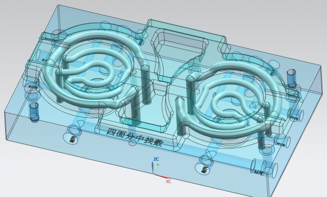
Channel Geometry Types: Which to Use and When
Beyond the four core parameters, the routing topology of the channel network determines how well cooling is distributed across the mold surface. Four main geometry types are used in production:
Series / Conformal Routing
- Single continuous channel, inlet to outlet
- Follows part contour at constant offset
- Simplest to design and validate
- Coolant heats progressively along path
- Outlet side ~2–5°C warmer than inlet
Spiral Channel
- Helical wrap around cylindrical cores/pins
- Uniform coverage of entire core surface
- No dead zones at core tip or sides
- Higher pressure drop than series routing
- Requires careful pitch spacing at tip
Zigzag / Baffle Pattern
- Alternating back-and-forth routing
- Good coverage of flat or gently curved areas
- Short pitch between passes
- Higher pressure drop than series
- Can cause coolant temperature stratification
TPMS Lattice Structure
- Gyroid, Schwartz, or Diamond surface lattice
- Maximum surface area-to-volume ratio
- Most uniform cooling of all geometries
- Requires specialized software (nTopology)
- More expensive: longer print time, higher cost
Parallel vs. series circuit layout
For any geometry type, the circuit layout (how channels connect to the coolant supply) is a separate decision from the routing topology:
- Series (single circuit): One channel from inlet to outlet. Simple connections, but coolant ΔT accumulates. Limited to circuit lengths where ΔT inlet-to-outlet stays below 5°C.
- Parallel (manifold): Multiple shorter circuits fed from a common manifold. Each circuit sees near-inlet-temperature coolant. Mandatory for large inserts or multi-zone temperature control.
- Rule of thumb: If a single circuit would exceed 800–1,000mm in total length at your target flow rate, split into parallel circuits.
Need channel design review before committing to print?
Send us your insert CAD and part geometry. Our engineers will review channel routing, flag issues, and confirm thermal analysis before manufacturing — free on first project.
Step-by-Step Design Workflow
A reliable conformal cooling design follows this sequence. Skipping steps — particularly thermal analysis and flow validation — is the most common cause of underperforming conformal systems.
Analyze part geometry for thermal hotspots
Before designing a single channel, run a baseline injection molding simulation (Moldflow or equivalent) on the part as-designed with no cooling or conventional cooling. Identify: (a) which zones have the highest temperature at end of pack, (b) where temperature uniformity is worst, (c) which zones are cooling-limited vs. fill-limited.
Output: Hotspot map with temperature values and locationsSelect channel geometry type for each zone
Map the geometry types to the hotspot zones: cylindrical cores get spiral channels, flat areas get series or zigzag, deep pockets get wrapped conformal routing. This is rarely one geometry type across the whole insert — complex mold designs will combine spiral (core) + series (cavity face) in the same insert.
Output: Geometry type map per zoneSet initial parameters from standard values
Start with the baseline: D = 8mm, W = 10mm (1.25×D), P = 20mm (2.5×D), R = 14mm (1.75×D). These are the conservative defaults. Zones with the highest temperature hotspots may warrant tightening W to 8mm and P to 16mm after structural check.
Output: Parameter set per zoneRoute channels in CAD
Model the channel centerlines as 3D spline curves in SolidWorks, NX, or Fusion 360. Sweep a circular profile along the centerline. Check: no channel intersects another, no channel wall is thinner than 0.8×D from adjacent channel, every channel segment has a clear powder evacuation route, all bends are ≥1.5×D radius.
Output: 3D insert CAD with internal channel geometryCalculate hydraulics and verify turbulent flow
For each circuit: calculate total channel length, determine required flow rate for Re > 10,000 (see hydraulics section below), verify pressure drop is within chiller capacity. If a single circuit is too long, split into parallel circuits.
Output: Flow rate spec per circuit, pressure drop estimateRun conformal cooling simulation
Simulate the designed conformal channel layout in Moldflow or equivalent. Compare: (a) mold surface temperature distribution vs. baseline, (b) cooling time vs. baseline, (c) ejection temperature vs. distortion limit. If hotspots remain, tighten W or P in those zones and re-simulate.
Output: Validated temperature map, predicted cycle timeDfAM check before sending to print
Verify all 3D printing constraints: no overhangs >45° inside channels, no blind dead-ends trapping powder, minimum channel diameter ≥4mm, no features too thin for structural integrity. This is typically done jointly with the SLM manufacturer during their DFM review.
Output: Print-ready CAD file, build orientation confirmedHydraulic Design: Flow Rate & Reynolds Number
The single most overlooked aspect of conformal cooling design is hydraulics. A beautifully routed channel network operating in laminar flow delivers 3–5× less heat transfer than the same geometry in turbulent flow. Laminar flow is the silent killer of conformal cooling performance.
Reynolds number calculation
The Reynolds number (Re) determines whether flow is laminar (<2,300), transitional (2,300–10,000), or turbulent (>10,000):
| Parameter | Symbol | Typical Value (water at 20°C) |
|---|---|---|
| Coolant velocity | v | Target ≥1.2 m/s for turbulent flow in 8mm channel |
| Channel diameter | D | 8 mm = 0.008 m |
| Kinematic viscosity (water 20°C) | ν | 1.004 × 10⁻⁶ m²/s |
| Re = v × D / ν | — | At v=1.2 m/s: Re = 1.2 × 0.008 / 1.004×10⁻⁶ ≈ 9,560 (transitional) |
| Required velocity for Re >10,000 | — | ≥1.26 m/s → flow rate ≥4.8 L/min for 8mm channel |
Practical flow rate targets by channel diameter
| Channel Diameter | Min. Flow Rate for Re = 10,000 | Recommended Flow Rate | Max Practical Pressure Drop (per circuit) |
|---|---|---|---|
| 6 mm | 2.8 L/min | 4–6 L/min | 3–4 bar |
| 8 mm (standard) | 4.8 L/min | 6–10 L/min | 2–3 bar |
| 10 mm | 6.3 L/min | 8–14 L/min | 1.5–2.5 bar |
| 12 mm | 7.5 L/min | 10–18 L/min | 1–2 bar |
Software Tools Used in Practice
| Software | Role in Conformal Cooling Design | Typical User |
|---|---|---|
| Autodesk Moldflow | Injection molding simulation; baseline hotspot analysis; conformal cooling thermal validation | Mold engineers, simulation specialists |
| SolidWorks | Channel CAD routing; insert design; DFM checks | Mold designers |
| Siemens NX | Same as SolidWorks — preferred in automotive sector | Mold designers (automotive) |
| Autodesk Fusion 360 | Integrated generative design + simulation; good for simpler designs | Smaller shops, startups |
| nTopology | TPMS lattice design for advanced conformal structures; field-driven design | Advanced AM design engineers |
| Materialise Magics | Build preparation, support structure generation, DfAM checks for SLM | AM build engineers at print facilities |
| ANSYS Fluent | Detailed CFD for coolant flow validation; pressure drop calculation | Simulation engineers (advanced projects) |
For 80% of production conformal cooling designs, Moldflow + SolidWorks is the practical combination. nTopology is becoming more common for complex geometric structures, but most mold shops have not yet integrated it into standard workflow. ANSYS Fluent is overkill for most projects — Moldflow's cooling simulation is sufficient for design validation. See our conformal cooling design software comparison for detailed cost and capability data on each platform.
The Five Design Mistakes That Kill Cooling Performance
Wall distance too large — "playing it safe" destroys effectiveness
Engineers often increase wall distance to 20–25mm "for structural safety." At this distance, cooling effectiveness drops to near-conventional levels. The structural concern is valid but should be addressed through material selection (18Ni300 for thin walls) and FEA validation — not by moving the channel further away.
✓ Fix: Keep wall distance at 1.0–1.5×D. Run FEA on thin walls rather than defaulting to thicker steel. Use 18Ni300 for high-stress inserts with tighter wall distances.Laminar flow — the silent performance killer
A channel operating at Re = 2,000 (laminar) transfers heat 3–5× less efficiently than the same channel at Re = 12,000 (turbulent). This is not visible without calculation — the channel appears to be flowing coolant, but heat transfer is ineffective. Common cause: specifying "standard chiller supply" without verifying flow rate per circuit.
✓ Fix: Calculate Re for every circuit. Specify minimum flow rate in design documentation. Pressure-test circuit at operating flow rate before mold trials.Dead-end channels — trapped powder causes blockage
Channels that terminate in a blind pocket cannot be cleared of sintered/partially-fused powder during or after printing. The blockage may not be obvious until the mold is on press and that zone fails to cool — showing up as a persistent hotspot identical to no cooling at all. Detected only by pressure-testing each circuit before delivery.
✓ Fix: Every channel section must have a clear powder exit. Design review must trace every channel from inlet to outlet and confirm no blind terminations. Always pressure-test circuits before shipping.Too-tight bend radius — stagnation zones at bends
Bends with radius <1×D cause flow separation on the outer wall of the bend. The separated flow region acts as a thermal insulator — the channel wall at that location effectively has no coolant contact. In a tightly-spaced design, multiple such bends can leave significant areas of the mold surface thermally isolated.
✓ Fix: Design all bends to ≥1.5×D radius. For complex routing where tight bends are unavoidable, increase local channel diameter slightly to preserve the 1.5×D ratio.Single series circuit for large inserts — outlet side runs hot
A single long circuit across a 300×300mm insert has 800–1,200mm of total channel length. With a 6 L/min flow rate, the coolant temperature rise from inlet to outlet is 8–12°C. The outlet half of the insert is operating with significantly degraded cooling — producing a systematic temperature gradient across the cavity surface that causes directional warpage.
✓ Fix: Split large inserts into parallel circuits with a manifold. Target ΔT <5°C inlet to outlet per circuit. For multi-cavity molds, ensure each cavity is on an independent circuit for temperature balance.Pre-Print Design Checklist
Use this checklist before sending any conformal cooling insert design to manufacturing:
- ✅Thermal validation done: Moldflow simulation confirms ≥30% cooling time reduction vs. baseline and surface temperature uniformity ≤±3°C
- ✅Wall distance verified: Channel centerline is ≥1.0×D from mold cavity surface everywhere in the design
- ✅Inter-channel wall verified: Minimum wall between adjacent channels is ≥0.8×D
- ✅Bend radius verified: All bends ≥1.5×D throughout the channel network
- ✅Powder evacuation: Every channel section has a clear exit path — no blind terminations
- ✅Overhang check: No internal overhangs >45° that would require support structures inside channels
- ✅Minimum diameter: All channels are ≥4mm diameter throughout (including transitions)
- ✅Reynolds number: At specified flow rate, Re >10,000 confirmed for every circuit
- ✅ΔT per circuit: Coolant temperature rise inlet-to-outlet is <5°C at specified flow rate
- ✅Pressure drop: Total pressure drop per circuit is within chiller pump capacity (typically <4 bar)
- ✅Fitting connections: Inlet/outlet locations accessible for connection; thread standard specified (BSP or NPT)
- ✅FEA on thin walls: Any wall thinner than 6mm has been structurally validated for injection pressure cycling
Real Design Example with Full Parameters
Project: PA66-GF30 Automotive Clip Bracket — 8-Cavity, Core Insert
Part Geometry
- Core depth: 52 mm
- Core diameter: 18 mm (oval cross-section)
- Nominal wall thickness: 3.0 mm
- Material: PA66-GF30 (mold temp: 80°C)
- Baseline cycle time: 42 seconds
- Baseline cooling time: 28 seconds (67% of cycle)
Channel Design Chosen
- Geometry: Spiral wrap on core
- Channel diameter (D): 8 mm
- Wall distance (W): 10 mm (1.25×D)
- Pitch: 18 mm (2.25×D)
- Bend radius: 14 mm (1.75×D)
- Total channel length: 640 mm per core
Hydraulic Design
- Flow rate: 7.0 L/min per circuit
- Velocity: 2.3 m/s
- Reynolds number: Re ≈ 18,300 (turbulent ✓)
- Pressure drop: 1.8 bar per circuit
- Coolant ΔT: 3.2°C (inlet to outlet ✓)
- Circuit layout: Series (640mm — within limit)
Simulation Results (Moldflow)
- Cooling time: 16.8 s (−40% vs 28 s baseline)
- Core tip temp reduction: 38°C → 4°C above mold avg
- Surface uniformity: ±2.1°C (vs ±11°C conventional)
- Warpage: 0.12 mm max (vs 0.68 mm conventional)
- Material: 18Ni300 (for thin walls at 10mm)
Want us to design and manufacture your conformal cooling insert?
Share your part file and current mold setup. We'll handle thermal analysis, channel design, DfAM review, SLM printing, and full post-processing — with a projected cycle time reduction before you commit.