Understanding how heat moves from the plastic part through the mold steel to the coolant explains every design and operating decision. The heat transfer pathway involves two mechanisms in sequence:
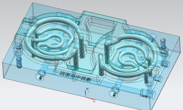
Conformal cooling channel design following part geometry for optimal heat transfer
Step 2: Forced ConvectionChannel wall → flowing coolant Governed by: Reynolds number (turbulent vs. laminar regime)
Why turbulent flow is not optional
Step 2 — convection from channel wall to coolant — is where most conformal cooling systems underperform. The heat transfer coefficient (h) in forced convection is proportional to the Nusselt number (Nu), which depends dramatically on the flow regime:
Flow Regime
Reynolds Number
Typical Nusselt Number
Relative Heat Transfer
Result
Laminar
<2,300
3.66 (constant wall temp)
1× (baseline)
Channels barely cool
Transitional
2,300–10,000
10–50
3–14×
Unpredictable, unstable
Turbulent
>10,000
50–200+
14–55×
Designed performance achieved
This is not a small difference. A conformal cooling system designed to deliver 40% cycle time reduction, operating in laminar flow, may deliver 5–10% at best. Every commissioning and maintenance decision flows from this single physical reality: keep the flow turbulent.
Why conformal channels outperform drilled channels on conduction
The conduction step (Step 1) is where conformal geometry wins over drilling. Heat conduction follows Fourier's Law: Q = k × A × ΔT / L. The critical variable is L — the thickness of steel between the channel and the cavity surface. A drilled channel sits 25–30mm from the mold surface. A conformal channel sits 8–12mm. With 420 stainless steel (k = 24 W/m·K), the conduction rate at 10mm wall distance is 2.5× higher than at 25mm. Combined with the surface area advantage of conformal routing, total heat extraction can be 3–4× higher than drilled channels at equivalent flow rate.
Channel Cross-Section Types & Thermal Performance
While circular channels are standard in SLM-printed conformal inserts, three cross-section types exist in the broader industry:
⭕
Circular (Standard)
The universal choice for SLM-printed conformal channels. Equal hydraulic diameter in all directions, straightforward to model and validate, no stress concentration points. Powder evacuation is reliable with proper exit routing.
Standard: 6–12mm diameter · As-built Ra 4–8μm
🔵
Streamlined / Teardrop
Elliptical or teardrop cross-section oriented with the narrow axis toward the mold surface. Reduces wall distance at the critical surface-facing side while maintaining structural thickness on the load-bearing sides. Higher surface area-to-volume ratio than circular.
Triply periodic minimal surface (gyroid, diamond, Schwartz-P). Extremely high surface area — 3–5× more than circular channels. Provides the most uniform temperature distribution achievable. Requires nTopology or equivalent for design; significantly more expensive.
Used in: optical, medical, ultra-precision molds · Premium cost, ~2–3× standard
For 90%+ of production applications, circular channels are the correct choice. The gains from streamlined or TPMS geometry are real but rarely justify the cost premium unless the application specifically demands maximum uniformity or the geometry forces a non-circular approach.
Coolant Temperature Settings by Plastic Material
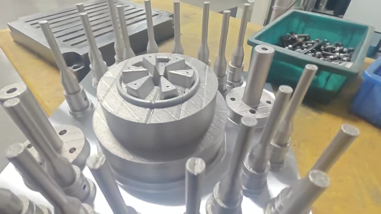
Variety of conformal cooling inserts with different channel configurations
Coolant temperature is set to achieve the target mold surface temperature at steady-state. The relationship is not one-to-one: a 20°C coolant does not produce a 20°C mold surface. The actual mold temperature depends on heat load, flow rate, wall distance, and chiller capacity. Use this table as a starting point, then verify with a thermocouple or thermal imaging camera during the first runs:
Requires high-temperature oil TCU. Conformal channels with CuCrZr inserts recommended.
TPU / TPE
20–40°C
10–25°C
Cold mold promotes rapid demold of flexible parts. Chilled water or glycol circuit.
Practical tip: During first production runs, attach a contact thermocouple to the mold surface near the hotspot identified in simulation. Run 20 shots, let it reach thermal equilibrium, then record the actual mold temperature. Adjust coolant temperature setpoint until actual mold surface temperature matches your target — do not assume coolant temp = mold temp.
Connecting to Your Chiller or Temperature Controller
Conformal cooling inserts connect to either a water temperature controller (WTC/chiller) for standard water-cooled applications, or a temperature control unit (TCU) with oil for mold temperatures above 90°C. The connection hardware and layout directly affects whether you achieve the designed flow rate.
Using 6mm hose on 8mm channel — creates restriction, reduces flow by 44%
Fittings
Full-bore ball valves + quick-disconnect; no restriction fittings
Using needle valves for "flow control" — creates turbulence dead zones
Thread standard
Match insert spec: BSP (G-thread, metric) or NPT (US standard)
Mixing thread standards with adapter fittings — leak risk under pressure
Manifold (parallel circuits)
Manifold bore ≥ sum of circuit diameters for equal flow distribution
Undersized manifold starves downstream circuits
Flow meter
Rotameter or turbine meter on each circuit; minimum resolution 0.5 L/min
No flow meter — cannot verify turbulent regime, no maintenance baseline
Pressure gauge
0–10 bar gauge on supply side per circuit
No pressure gauge — cannot detect scaling or blockage early
Critical installation rule: Install a dedicated flow meter and pressure gauge on every conformal cooling circuit. Without a flow rate baseline established at commissioning, you cannot detect the gradual performance degradation from scaling or partial blockage that will occur over months of operation. A 15% flow rate drop is your trigger for cleaning — but you can only detect it if you measured the baseline.
Commissioning Protocol: 5 Steps Before First Shot
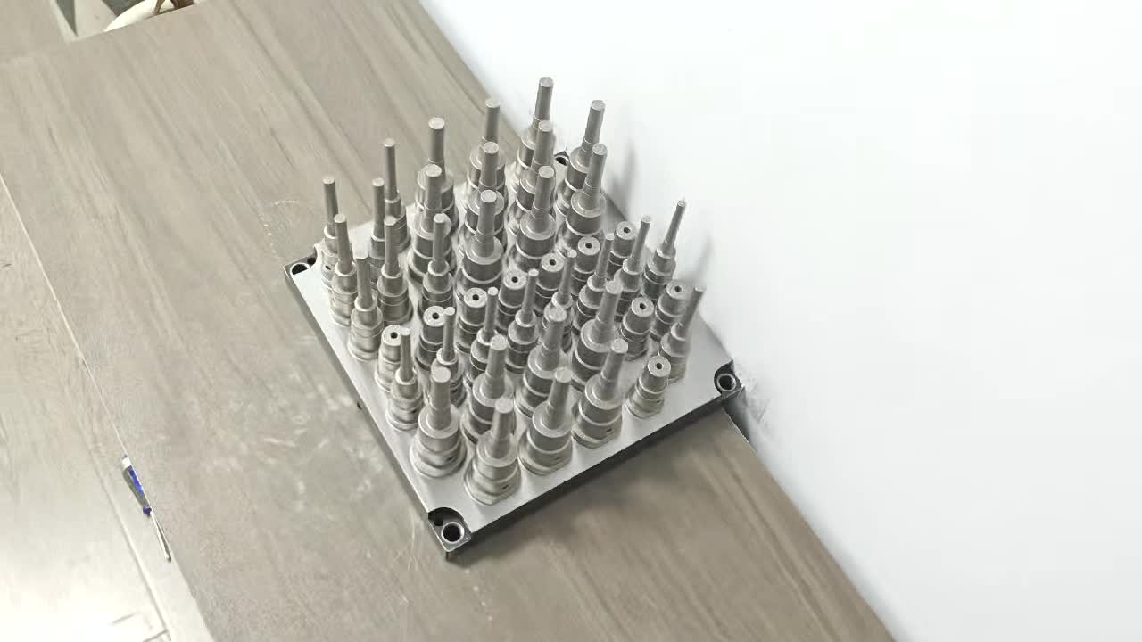
Metal 3D printing enables complex internal cooling channel geometries
These five steps must be completed before the mold goes into production. Skipping them is the leading cause of "conformal cooling didn't work" complaints — which, on investigation, almost always turn out to be commissioning failures, not design or manufacturing failures.
1
Pressure test all circuits
Cap one end of each circuit. Apply compressed air at 1.5× operating pressure (typically 6–9 bar) for 10 minutes. Zero pressure drop = pass. Any pressure drop indicates a leak — at a fitting connection, thread joint, or (rarely) a crack in the insert wall. Do not run water until this test passes.
✓ Pass: Zero pressure drop over 10 minutes✗ Fail: Locate leak with soapy water spray; re-seal or replace
2
Flush with clean water
Run clean water at maximum available flow rate through each circuit for 5 minutes before connecting to chiller. This flushes any residual metal particles, machining coolant, or assembly lubricant from the channels. Inspect discharge water — it should run clear within 2 minutes. Discolored water after 5 minutes indicates contamination requiring extended flushing.
✓ Pass: Clear discharge water within 5 minutes✗ Fail: Continue flushing; if still discolored after 20 min, investigate channel condition
3
Measure and record baseline flow rate per circuit
Connect to chiller at operating pressure. Read flow rate on each circuit meter. Confirm each circuit meets the minimum flow rate for turbulent regime (Re >10,000 — for 8mm channels, minimum 4.8 L/min; recommended 6–10 L/min). Record these baseline values. This is your reference — any future reading 15% below baseline triggers cleaning.
Run thermal equilibration and verify mold surface temperature
Set chiller to target coolant temperature. Run cooling system for 30 minutes with no injection (mold closed, press idle). Then measure mold cavity surface temperature with a contact thermocouple at the previously identified hotspot location. Record actual mold surface temperature vs. target. Adjust chiller setpoint until actual = target ±5°C.
✓ Pass: Mold surface temperature within ±5°C of target after 30 min equilibration✗ Fail: Check flow rates, chiller capacity, and verify correct coolant temperature setpoint
5
First shot thermal imaging baseline
After 20 production shots at steady state, open the mold between cycles and immediately capture a thermal image (infrared camera) of the cavity surface. This image becomes your permanent benchmark. Any future production quality issue can be compared to this baseline image — if the thermal pattern has changed, you've identified where the cooling degradation is occurring.
✓ Pass: Thermal image captured and filed; temperature uniformity ≤±5°C across cavity✗ Fail if uniformity >±8°C: Investigate channel design or flow rate issues before full production
Receiving a conformal cooling insert for the first time?
We provide a commissioning data sheet with every insert we ship: baseline flow rate spec, pressure test certificate, recommended coolant temperature by material, and maintenance intervals. Ask for it when ordering.
Coolant Specification: What to Use and What to Avoid
The single most underspecified aspect of conformal cooling operation is coolant quality. Poor water quality causes scaling that degrades performance faster than any design factor — and it's entirely preventable.
Parameter
Acceptable Range
Warning Range
Action
Water hardness (CaCO₃)
0–100 ppm
100–200 ppm
Softened or DI water recommended above 150 ppm
pH
6.5–8.5
<6.0 or >9.5
Acidic water corrodes channels; alkaline causes scale
Chloride content
<50 ppm
50–200 ppm
Chlorides attack stainless steel; use DI water for 420 SS inserts
Rust inhibitor
2–5% by volume
None
Without inhibitor, iron particles circulate and deposit; always use
Coolant temperature (water)
10–90°C
>90°C
Above 90°C: switch to oil-based TCU fluid
Freeze protection
Glycol mix if ambient <5°C
Pure water in cold shop
Freezing in channels causes insert cracking
Hard water is the #1 enemy of conformal cooling performance. At 300 ppm hardness (common tap water), calcium carbonate begins scaling channel walls within weeks. A 1mm scale layer on a 10mm steel wall increases effective thermal resistance by ~30% — equivalent to moving the channel 3mm further from the mold surface. Use deionized or softened water, always with rust inhibitor.
Maintenance Schedule & Chemical Descaling Procedure
Weekly
Operational checks
Visual check for leaks at all fittings
Verify chiller temperature setpoint is holding
Check coolant level in chiller reservoir
Note any change in part quality or cycle time
Every 3–6 Months
Flow rate verification
Measure flow rate on each circuit
Compare to commissioning baseline
If any circuit <85% of baseline → immediate chemical clean
Test coolant pH and inhibitor concentration
Top up or replace inhibitor as needed
Annually (or per trigger)
Full cleaning & inspection
Chemical descaling (see procedure below)
Pressure test all circuits after cleaning
Thermal imaging during production run
Compare thermal image to commissioning baseline
Inspect all fittings; replace O-rings if needed
Chemical descaling procedure
Use this procedure when flow rate drops >15% from baseline, or as part of annual maintenance:
Isolate the mold from the production circuit. Cap outlet connections.
Prepare descaling solution: 5–10% citric acid in water (pH 2–3). Citric acid is effective against calcium carbonate and safe for 420 SS and 18Ni300 steel. Do not use hydrochloric acid — it attacks stainless steel and causes pitting.
Circulate the solution through all channels at 2–4 L/min for 2–4 hours. The solution will react with calcium deposits (fizzing indicates active descaling).
Flush with clean water at maximum flow rate for 10 minutes until pH of discharge water returns to neutral (pH 6.5–7.5).
Pressure test all circuits to confirm no descaling has exposed any pre-existing micro-cracks or weakened areas.
Reconnect and re-establish flow rate baseline. If flow rate is still below 90% of original baseline after descaling, suspect mechanical blockage (sintered powder or corrosion debris) — requires mechanical cleaning or borescope inspection.
Switch to DI water + fresh inhibitor after cleaning to prevent rapid re-scaling.
Thermal imaging; borescope inspection; pressure test
Chemical descaling; if still blocked, mechanical clearing (pressure flush or wire)
Gradual cycle time increase over months
Scaling reducing heat transfer — common in hard water areas
Flow rate drop >15% from baseline
Chemical descaling; switch to DI water + inhibitor
Cavity-to-cavity temperature imbalance
Unequal flow between parallel circuits; one circuit partially blocked
Measure flow rate on each circuit independently
Balance flow by adjusting circuit-level ball valves; clean low-flow circuit
Water dripping from parting line during production
Channel wall failure (crack) or fitting leak
Pressure test off-press; identify which circuit drops pressure
Fitting: re-seal with PTFE and re-test. Channel crack: insert must be replaced or repaired by laser welding
Warpage worse than simulation predicted
Coolant temperature too high; insufficient flow rate; incorrect chiller setpoint
Contact thermocouple on mold surface; compare actual vs. target temp
Lower coolant setpoint; verify flow rate; check chiller cooling capacity vs. actual heat load
Burn marks reappearing after conformal upgrade
Mold surface temp still too high in specific zone; incomplete cooling upgrade
Thermal imaging to locate specific hotspot
Verify that conformal channel covers that specific zone; check for dead zone at nearby tight bend
Chiller running at full capacity but mold still too hot
Chiller undersized for actual heat load; or heat load higher than estimated
Calculate part heat load: Q = mass × Cp × ΔT × shots per hour
Increase chiller capacity; split into two chiller circuits; reduce shot rate until chiller catches up
Rust-colored water in coolant lines
Corrosion inside channels or in chiller system; no inhibitor or inhibitor depleted
pH and inhibitor test; flush and examine discharge color
Full flush; add/replace rust inhibitor at 3–5%; switch to DI water if using tap water
Flow rate reads zero on one circuit after maintenance
Ball valve left closed; fitting cross-threaded blocking flow; hose kinked
Trace circuit manually from inlet to outlet
Open valves; inspect fittings; straighten hose routing
Channel Lifespan and How to Extend It
A well-designed, well-maintained conformal cooling insert should outlast the mold itself — typically 500,000 to 1,000,000+ shots with no loss of cooling performance. In practice, premature failures occur due to four mechanisms:
Failure Mechanism
Typical Onset
Prevention
Scaling / fouling
3–12 months with hard water
DI water + inhibitor; chemical clean every 12–18 months
Lifespan extension summary: DI water + rust inhibitor, annual chemical descaling, and a 50-micron filter in the coolant circuit will extend conformal insert lifespan from a typical 300K–500K shots (tap water, no maintenance) to 1M+ shots. The cost of water treatment is measured in dollars per year; the cost of an insert replacement is measured in thousands.
Every MouldNova Insert Ships with a Commissioning Data Sheet
Baseline flow rate spec, pressure test certificate, coolant temperature recommendations by material, and maintenance schedule — included with every order. We don't just manufacture the insert; we help you operate it correctly.
How do conformal cooling channels transfer heat from the mold?
Two mechanisms in sequence: Conduction — heat moves from the mold cavity surface through the steel wall to the channel wall; governed by steel thermal conductivity (~24 W/m·K for 420 SS) and wall thickness. Forced convection — heat moves from the channel wall to the flowing coolant; governed by Reynolds number. Turbulent flow (Re >10,000) gives 14–55× better heat transfer than laminar flow. Both steps must be optimized: conformal routing minimizes conduction wall thickness; correct flow rate ensures turbulent convection.
What coolant temperature should I set for conformal cooling channels?
Coolant temperature is set to achieve your target mold surface temperature, not as an absolute value. Starting points: ABS 25–60°C coolant, PP 15–40°C, PC 60–100°C (oil TCU above 90°C), Nylon PA66 40–70°C, PEEK 140–180°C (oil). Verify actual mold surface temperature with a thermocouple during commissioning — adjust chiller setpoint until actual mold temp = target ±5°C.
How often should conformal cooling channels be cleaned?
With DI water + inhibitor: flow rate check every 6 months, chemical descaling every 18–24 months. With tap water (100–200 ppm): flow rate check every 3 months, descaling every 6–12 months. With hard water (>200 ppm): descaling every 3–4 months. Trigger point regardless of schedule: any circuit flow rate drops >15% from commissioning baseline → immediate descaling.
What causes conformal cooling channels to underperform after installation?
Four common causes: (1) Laminar flow — flow rate below turbulent threshold, reducing heat transfer by 3–5×; verify Re >10,000. (2) Scaling — calcium deposits from hard water insulating channel walls; chemical descaling required. (3) Partial blockage from residual powder — should be caught in pressure testing before delivery; requires mechanical clearing. (4) Chiller undersized — actual mold heat load exceeds chiller capacity; coolant heats up during production.
How long do conformal cooling channels last?
500,000–1,000,000+ shots with correct design and maintenance. Key factors limiting lifespan: scaling/fouling (prevented by DI water + inhibitor), corrosion/pitting (prevented by correct pH and chloride levels), fatigue cracking (prevented by correct wall thickness ≥1×D at design stage), and erosion from abrasive coolant (prevented by a 50-micron filter in the coolant circuit). Cost of proper water treatment: $50–200/year. Cost of insert replacement: $800–9,000+.