Conformal Cooling Channels in Plastic Injection Molding: Design, Performance, and ROI
- Why cooling dominates the injection molding cycle — and what Moldflow tells us about it
- Four specific ways conventional straight-drilled channels fail injection molding operations
- How conformal channels solve each of those four problems
- Channel geometry types for injection molding, with a decision table for 5 configurations
- Design parameters: diameter, pitch, depth, and Reynolds number targets for molding
- Resin-specific cooling requirements — PP through TPE with mold temperature and minimum cooling time
- Machine integration: flow rate, pressure rating, and temperature controller selection
- Real production data across 6 injection molding applications
- Cost-benefit payback calculator for molding shops at various shot volumes
Table of Contents
- How Cooling Channels Fit Into the Injection Molding Cycle
- Four Ways Conventional Channels Fail Injection Molding
- How Conformal Channels Solve Each Problem
- Channel Geometry Types for Injection Molding
- Design Parameters for Injection Molding Cooling Channels
- Resin-Specific Cooling Requirements
- Integration with Injection Molding Machines
- Real Production Data: 6 Injection Molding Applications
- Cost-Benefit Calculation for Molding Shops
- FAQ
How Cooling Channels Fit Into the Injection Molding Cycle
The injection molding cycle has four phases: fill, pack/hold, cooling, and ejection. Of these, cooling is overwhelmingly the dominant phase in terms of time — and therefore in terms of cost per part. Understanding why this is true, and what controls it, is the foundation for understanding what conformal cooling channels actually accomplish.
The 50–70% figure is not arbitrary. It is determined by the physics of heat extraction: the plastic enters at melt temperature (220–320°C depending on resin) and must be cooled to a temperature where it can sustain ejection forces without deforming — the ejection temperature, which is typically 40–80°C below the heat deflection temperature. The rate at which this heat can be removed is governed entirely by the cooling channel geometry.
What Moldflow Data Shows About Cooling Time vs. Part Complexity
Moldflow cooling analysis consistently shows that cooling time scales nonlinearly with part complexity. For a simple flat plaque, a straight-drilled channel 25 mm from the surface achieves acceptable temperature uniformity. Add a 15 mm rib and the analysis shows a hot zone at the rib tip that requires 40–60% more cooling time than the flat wall — even though the rib represents a tiny fraction of total part volume.
The reason: heat in the rib tip has nowhere to go except through the mold steel sidewall, laterally to the nearest cooling channel. The thermal path length is 3–5× longer than from the flat wall, and heat flux density at the rib tip is higher (concentrated geometry). This forces designers to set the overall cooling time based on the worst-case zone, not the average.
Moldflow studies on complex consumer electronics housings (wall thickness 1.5–2.5 mm, multiple snap-fit features) show cooling time as a function of mold temperature uniformity: a ΔT of 15°C between hot and cold zones (typical for drilled channels) requires 28–35 seconds of cooling. Reducing ΔT to 3–5°C via conformal channels reduces required cooling time to 16–22 seconds — a 35–40% reduction on cooling time alone, translating to 22–28% total cycle time reduction.
Four Ways Conventional Straight-Drilled Channels Fail Injection Molding
Straight-drilled cooling channels have served injection molding for decades, and for simple flat parts with generous wall thickness, they work adequately. But production injection molding increasingly involves complex geometry, tight tolerances, and high cavitation — four specific failure modes appear repeatedly.
Problem 1: Hot Spots at Cores, Ribs, and Bosses
A drill bit travels in a straight line. Cores, ribs, and deep bosses extend into the mold in three dimensions that a drill cannot follow. The nearest cooling channel may be 30–50 mm away from a rib tip. That distance creates a zone where mold temperature runs 15–25°C above the cooled cavity wall — a hot spot that forces longer cooling and causes differential shrinkage.
Problem 2: ΔT Across Cavity Surface Causes Warpage
Even without cores, a drilled channel grid creates alternating bands of well-cooled and poorly-cooled surface. The temperature variation between the area above a channel and the midpoint between two channels is typically 8–14°C. This ΔT causes differential shrinkage in the solidifying plastic — one side shrinks more than the other, producing internal stress that becomes warpage after ejection. In dimensionally critical parts (automotive clips, medical connectors), this variation alone causes dimensional failures.
Problem 3: Pressure Drop Limits Flow Rate in High-Cavitation Molds
In 32-, 64-, or 128-cavity molds, coolant must be distributed through a manifold to many channels in parallel. Each drilled channel circuit adds pressure drop, and the manifold itself adds significant restriction. At high cavitation, total system pressure drop often forces the operator to reduce flow rate below the turbulent threshold (Re < 4,000), dropping heat transfer efficiency by 30–50% and making it impossible to reach steady-state cooling without extended cycle times.
Problem 4: Cycle Time Optimization Plateau After Initial Setup
With conventional channels, cycle time optimization follows a diminishing returns curve. After the initial setup — adjusting coolant temperature, flow rate, and mold temperature controller set point — most of the achievable benefit is captured within the first 50 production hours. Further reduction requires changes to the mold itself. Without the geometry flexibility of conformal channels, the mold has simply reached its thermal ceiling. Further investment in chiller capacity or flow rate yields no improvement because the bottleneck is wall distance to the hot zone, not coolant capacity.
These four failure modes interact. A mold with hot spots at cores (Problem 1) will have high ΔT (Problem 2) and will compensate with extended cycle time that only partly masks the warpage issue (Problem 4). High-cavitation molds experience all four simultaneously.
How Conformal Cooling Channels Solve Each Problem
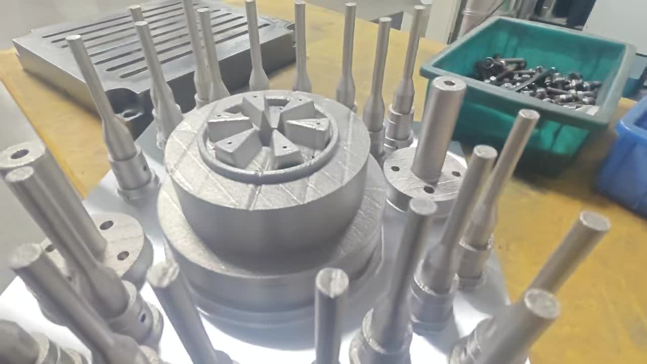
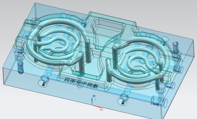
Conformal cooling channels — manufactured via Laser Powder Bed Fusion (LPBF) metal 3D printing and fitted as inserts into pockets in P20 or H13 parent molds — address each failure mode at its root cause rather than compensating for it elsewhere in the process.
Solution 1: Channels Follow Every Core and Rib Contour
LPBF printing is unconstrained by drill geometry. Channels can spiral around a core pin, run through a rib at 1.5× channel diameter from the surface, and follow complex 3D curves that no cutting tool can reach. Hot spot temperature at a rib tip drops from 185°C to 145–155°C. The worst-case cooling zone is no longer the constraint on cycle time.
Solution 2: Uniform Wall Distance Reduces ΔT to 2–5°C
Because conformal channels maintain constant pitch and constant depth from the cavity surface across the entire insert, the temperature field at the cavity wall becomes uniform. Moldflow validation of conformal inserts routinely shows ΔT of 2–5°C versus 12–18°C for drilled channels on the same part. Differential shrinkage drops proportionally. Warpage on a 200 mm automotive clip that measured 0.8 mm with drilled channels drops to 0.1–0.2 mm with conformal cooling — within specification without process adjustment.
Solution 3: Independent Circuit per Insert Bypasses Manifold Pressure Drop
In high-cavitation molds, each conformal insert carries its own independent cooling circuit with dedicated inlet and outlet. Instead of one manifold branching to 64 channels with accumulated pressure drop, there are 64 independent short circuits — each with low pressure drop and individually controllable. Flow rate per channel is maintained in turbulent regime (Re 4,000–8,000) regardless of cavitation count. Across a 64-cavity closure mold, this reduces per-cavity coolant transit time from 18 seconds to 11 seconds.
Solution 4: Thermal Ceiling Is Raised; Optimization Continues
After conformal insert installation, cycle time optimization resumes because the thermal ceiling has moved. Operators find additional 5–10% cycle time gains during the first 500 production hours as they fine-tune coolant temperature, flow rate, and cooling time setpoint against the new thermal reality. The hot spots that previously locked cycle time in place are eliminated, enabling the full potential of the machine to be used.
Channel Geometry Types for Injection Molding Applications
Not every conformal cooling geometry is appropriate for every injection molding application. The five main configurations each have a context where they perform best, a complexity level, and a realistic expectation for cavity surface temperature improvement.
| Geometry Type | Best Injection Molding Use Case | Design Complexity | ΔT Improvement vs. Drilled | Notes |
|---|---|---|---|---|
| Straight / Parallel Conformal | Flat cavity plates, large-area packaging closures, shallow draw parts | Low | 30–50% ΔT reduction | Easiest to design and depowder; limited benefit for 3D geometry. Use when geometry is simple and cost is the primary constraint. |
| Conformal Serpentine | Deep-draw housings, enclosures, single-face inserts with moderate 3D contour | Medium | 45–60% ΔT reduction | Most common configuration. Good balance of thermal performance, depowdering ease, and design time. Standard choice for electronics shells and appliance panels. |
| Conformal Spiral Core | Core pins >8 mm diameter, deep bosses, threaded cores in medical and automotive | Medium | 55–70% ΔT reduction at core tip | Helical channel winds around core from base to tip. Requires internal powder removal port. Material: CuCrZr preferred for high-temperature resins. |
| Conformal Cavity-Follow | Complex multi-surface parts — bumper brackets, instrument panel trim, medical device housings | High | 60–75% ΔT reduction | Channel network follows the 3D surface at constant offset. Requires CFD validation of flow distribution. Highest performance; requires experienced design team. |
| TPMS Insert (Gyroid / Schwartz D) | High-heat-load zones: sprue area, gate area, thick-section transitions, hot-runner manifold blocks | High | 70–85% ΔT reduction in insert zone | Triply periodic minimal surface lattice maximizes surface area per unit volume. Highest heat transfer coefficient. Powder removal is most challenging — dedicated process required. |
Design Parameters for Injection Molding Cooling Channels
Injection molding imposes specific constraints on cooling channel design that differ from die casting or other applications. Shot weights from 0.5 g (miniature medical connectors) to 5 kg (automotive structural parts) span four orders of magnitude, but the governing channel geometry parameters converge to a relatively narrow range in molding practice.
Calculating Minimum Flow Rate for Turbulent Regime
For an 8 mm channel with water at 20°C (kinematic viscosity ν = 1.004 × 10³ mm²/s), the minimum flow velocity for Re = 4,000 is:
Flow rate Q = v × A = 0.50 × π/4 × (0.008)² = 0.000025 m³/s = 1.51 L/min
For a 6 mm channel: vmin = 0.67 m/s, Qmin = 1.13 L/min. Smaller channels need less absolute flow rate to achieve turbulence — a useful design lever when machine coolant supply is limited.
The Re = 4,000–8,000 range is specifically calibrated for injection molding, where thermal cycling loads are lower than die casting and pressure ratings are typically 15–20 bar maximum. Above Re 8,000 in a 6–8 mm channel, the pressure drop penalty across a 200–400 mm insert becomes significant and may exceed the capacity of a standard TCU pump.
Wall Thickness Between Channel and Cavity Surface
The minimum wall between the channel wall and the cavity surface must satisfy two criteria simultaneously: sufficient mechanical strength to resist cavity pressure (typically 800–1,500 bar for injection molding), and adequate thermal path to enable heat extraction. For 420SS inserts in injection molding, a minimum wall of 1.0 × D (8 mm for an 8 mm channel) is structurally conservative. Below 0.8 × D, FEA validation of fatigue life is mandatory, particularly for high-cycle applications (>500,000 shots/year).
Resin-Specific Cooling Requirements
Cooling channel design cannot be divorced from material properties. The mold temperature required for a given resin — set by its crystallization kinetics (semi-crystalline) or glass transition temperature (amorphous) — directly determines the coolant temperature target, and therefore the temperature differential driving heat removal. Six resins cover the vast majority of injection molding production volume.
| Resin | Type | Mold Temp (°C) | Cooling Water Temp (°C) | Min. Cooling Time* | Key Considerations |
|---|---|---|---|---|---|
| PP (Polypropylene) | Semi-crystalline | 20–60 | 10–20 | 8–18 s/mm wall | High crystallinity sensitivity — hot spots produce amorphous zones with 1–2% higher shrinkage than surrounding crystalline regions. ΔT directly causes warpage in closures and thin-wall packaging. Fastest payback at high volumes. |
| ABS (Acrylonitrile Butadiene Styrene) | Amorphous | 40–80 | 20–35 | 10–22 s/mm wall | Less crystallinity-driven warpage than PP; primary issue is sink marks and surface gloss variation from ΔT. Conformal cooling improves surface quality as much as dimensional accuracy. Common in electronics and consumer goods. |
| PC (Polycarbonate) | Amorphous | 80–120 | 50–80 | 18–35 s/mm wall | High mold temperature required for optical clarity and surface finish. ΔT creates birefringence (stress-induced optical distortion) in transparent parts. CuCrZr inserts recommended — the elevated coolant temperature reduces the thermal gradient potential, making high-conductivity channels essential for meaningful ΔT reduction. |
| PA66 (Nylon 66) | Semi-crystalline | 60–100 | 30–60 | 15–28 s/mm wall | Crystallization rate is temperature-dependent — rapid quench below 60°C creates different microstructure than controlled cooling above 80°C. Specifying conformal channel cooling requires agreement on whether to maximize crystallinity (structural parts) or minimize cycle time (commodity parts). Glass-filled grades (PA66-GF30) have lower shrinkage but are more warpage-prone from ΔT. |
| POM (Acetal / Delrin) | Semi-crystalline | 60–100 | 30–55 | 12–25 s/mm wall | Very high crystallinity (70–80%) makes POM extremely sensitive to hot spots — dimensional variation from a 10°C hot spot can reach ±0.2 mm on a 50 mm dimension, violating gear mesh tolerances. Conformal cooling for POM precision gears delivers ΔT < 3°C, enabling first-article pass rates > 95%. |
| TPE (Thermoplastic Elastomer) | Block copolymer | 20–50 | 10–25 | 20–40 s/mm wall | Long cooling time due to low thermal conductivity of elastomeric phase. Overmolded components (TPE over PP or PC substrate) require matched cooling rates between materials to prevent delamination. Conformal channels in both cavity and core inserts enable independent temperature control of each surface. High cycle time benefit per unit insert cost. |
* Minimum cooling time per mm of nominal wall thickness at recommended mold temperature, assuming turbulent coolant flow in conformal channels. Conventional drilled channels typically add 40–70% to these figures.
Integration with Injection Molding Machines
Conformal cooling inserts do not function in isolation — they are part of a thermal system that includes the injection molding machine's cooling infrastructure. Getting this integration right is as important as the insert design itself.
Flow Rate Requirements
Each conformal insert circuit requires 0.5–3 L/min of coolant flow to maintain turbulent regime, depending on channel diameter and length. For a 48-cavity closure mold with one conformal insert per cavity, total required flow rate is 24–144 L/min — which must be verified against the mold temperature controller's pump capacity before ordering inserts. Most standard TCUs (temperature control units) are rated for 20–40 L/min. High-cavitation molds require either multiple TCUs, a central chiller with high-capacity pump, or a circuit manifold that groups inserts into 6–8 parallel circuits sharing a single TCU port.
Pressure Rating
Conformal cooling channels in LPBF-printed 420SS inserts are rated to maximum 15–20 bar working pressure in injection molding service. This is sufficient for standard mold temperature controllers (operating at 3–8 bar) and most chillers (operating at 5–12 bar). High-pressure applications — such as steam-heated molds (above 150°C) or specialized overpressure TCUs — require confirmation against the specific insert wall thickness and material. CuCrZr inserts have lower yield strength than 420SS and may require pressure de-rating at elevated temperatures.
Temperature Controller Selection: Chiller vs. TCU vs. Tower Water
| Cooling System | Temperature Range | Best Resin Applications | Flow Rate (typical) | Pressure (typical) | Notes |
|---|---|---|---|---|---|
| Chiller (refrigerated) | 5–35°C | PP, ABS, TPE — maximum cycle time reduction | 20–200 L/min | 4–10 bar | Required for full cycle time benefit on high-volume PP and ABS molds. Condensation risk in humid environments — insulate external plumbing. Most ROI-sensitive option. |
| TCU (Temperature Control Unit) | 20–160°C | PC, PA66, POM — elevated mold temperature control | 15–50 L/min | 3–8 bar | Standard for engineering resin molds. Oil-based TCUs used above 90°C. Most compatible with conformal inserts. Allows setpoint-controlled mold temperature to ±1°C. |
| Tower Water (plant cooling) | 18–32°C (seasonal variation) | PP, ABS commodity molds — lowest cost operation | 50–500 L/min | 2–5 bar | Lowest operating cost but uncontrolled temperature variation affects cycle time stability. Hard water (above 200 ppm CaCO&sub3;) causes scaling in conformal channels — water treatment required. Not recommended for precision parts. |
Real Production Data: 6 Injection Molding Applications
The following data is drawn from production installations where conformal cooling inserts were retrofitted into existing P20 or H13 parent molds. Cycle times are measured at steady-state production — not first-article conditions. ΔT is measured by thermal imaging after 30 minutes of continuous production. Scrap rate is calculated over the first 30,000 shots post-installation versus the preceding 30,000 shots conventional.
| Application | Resin | Cavitation | Cycle Time Before | Cycle Time After | Reduction | ΔT Before / After | Scrap Rate Before / After |
|---|---|---|---|---|---|---|---|
| Automotive bumper bracket | PP-GF20 | 2-cavity | 52 s | 33 s | 37% | 19°C / 4°C | 4.2% / 0.8% |
| Electronics connector housing | PA66-GF30 | 16-cavity | 38 s | 22 s | 42% | 22°C / 3°C | 6.1% / 0.6% |
| Medical catheter hub | PC (USP Class VI) | 8-cavity | 44 s | 29 s | 34% | 16°C / 3°C | 3.8% / 0.4% |
| Packaging closure (flip-top cap) | PP | 64-cavity | 18 s | 11 s | 39% | 14°C / 5°C | 1.9% / 0.5% |
| Consumer electronics shell | ABS/PC blend | 4-cavity | 35 s | 23 s | 34% | 18°C / 4°C | 5.3% / 0.9% |
| Appliance structural component | POM | 8-cavity | 48 s | 30 s | 38% | 21°C / 3°C | 7.4% / 0.7% |
Across these six applications, cycle time reduction ranges from 34% to 42%, with a mean of 37.3%. ΔT reduction is consistently from 14–22°C down to 3–5°C. Scrap rate reduction is the most variable benefit — high initial scrap rates (appliance POM at 7.4%, electronics connector at 6.1%) reflect parts that were previously struggling at specification limits and that conformal cooling moves comfortably within tolerance.
Need conformal cooling channels for your injection mold?
MouldNova designs and manufactures LPBF-printed conformal cooling inserts for P20 and H13 parent molds. We include Moldflow validation, pressure testing, and cycle time projection as standard.
Cost-Benefit Calculation for Injection Molding Shops
The economic case for conformal cooling channels depends on three variables: annual shot volume, baseline cycle time, and machine hourly rate. For a detailed pricing breakdown, see our conformal cooling cost guide. The calculation below uses a standard injection molding machine rate of $75/hour — representative of a 150–400-ton machine including operator, overhead, and depreciation in North American or Western European operations. Asian operations with lower machine rates should scale linearly.
The Base Calculation
Assume: baseline cycle time 30 seconds, 35% cycle time reduction (conservative from our production data), 1-cavity mold, machine rate $75/hr, conformal insert cost $10,000 (single cavity, moderately complex geometry).
Scenario A: 250,000 shots/year (low volume)
Scenario B: 500,000 shots/year (medium volume)
Scenario C: 100,000 shots/year (high-value, low volume)
Payback at Various Annual Shot Volumes — Summary Table
| Annual Shot Volume | Cycle Time Saved / Shot | Machine Hours Saved / Year | Annual Savings (@ $75/hr) | Insert Cost (est.) | Payback Period |
|---|---|---|---|---|---|
| 50,000 | 10.5 s (35% of 30 s) | 146 hrs | $10,950 | $8,000–12,000 | 8–13 months |
| 100,000 | 10.5 s | 292 hrs | $21,875 | $8,000–12,000 | 4–7 months |
| 250,000 | 10.5 s | 729 hrs | $54,688 | $8,000–12,000 | 2–3 months |
| 500,000 | 10.5 s | 1,458 hrs | $109,375 | $8,000–15,000 | < 2 months |
| 1,000,000 | 10.5 s | 2,917 hrs | $218,750 | $10,000–20,000 | < 6 weeks |
| 2,000,000+ | 10.5 s | 5,833 hrs | $437,500 | $10,000–20,000 | < 3 weeks |
Assumptions: 30-second baseline cycle, single-cavity mold, 35% cycle time reduction, machine rate $75/hr. Multi-cavity molds multiply savings by cavitation count. Scrap rate savings, quality-related customer credits, and capacity freed for additional production are not included — all add to the real return.
When Conformal Cooling Is Not the Right Answer
Not every mold benefits equally. Three scenarios where the economics are weaker:
- Prototype or low-volume tools (< 10,000 shots/year): Payback extends beyond 2 years and does not justify the engineering investment. Use P20 machined channels or use a temporary mold entirely.
- Simple flat parts with wall thickness < 1 mm and no cores: Conventional channels already perform well on flat geometry. The ΔT difference between conventional and conformal is small, and cycle time is already short (< 10 seconds). ROI is marginal.
- Molds where the machine, not the cooling, limits throughput: If your injection speed or clamp force is the constraint, improving cooling does not increase output. Diagnose the true bottleneck before investing in conformal channels.
Frequently Asked Questions
What percentage of the injection molding cycle is spent on cooling?
Why do conventional straight-drilled cooling channels cause warpage in injection-molded parts?
What is the correct channel diameter for conformal cooling channels in injection molds?
How quickly does conformal cooling pay back its cost in an injection molding shop?
Which resins benefit most from conformal cooling channels in injection molding?
Related Resources
- Conformal Cooling Channels: How They Work, How to Commission & Maintain Them
- Conformal Cooling Channel Design: Parameters, Geometry Types & Engineering Guide
- Conformal Cooling in Injection Molding: Cycle Time, Cost & Real Factory Data
- Conformal Cooling Mold Buyer's Guide
- MouldNova Conformal Cooling Insert Services