1. The Cooling Problem in Injection Moulding
Cooling is the dominant phase in the injection moulding cycle. For most thermoplastic parts, cooling accounts for:
| Cycle Phase | Typical % of Cycle | Can It Be Reduced? |
|---|---|---|
| Mould close + injection | 5–10% | Limited (machine speed) |
| Packing / holding | 10–20% | Limited (material dependent) |
| Cooling | 50–70% | Yes — this is where conformal cooling acts |
| Mould open + ejection + close | 10–15% | Marginal (automation) |
The practical implication: cooling is by far the largest single opportunity to reduce cycle time. A 40% reduction in cooling time (achievable with conformal cooling on most parts) translates to a 20–28% total cycle time reduction — the equivalent of adding 20–28% more machine capacity without buying a single new press.
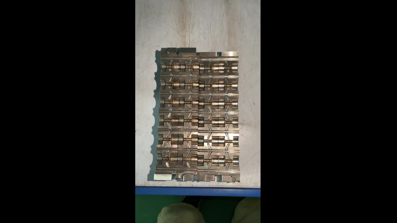
2. Why Conventional Straight-Drilled Channels Are Limited
Traditional mould cooling uses straight channels drilled from the outside of the mould block. This approach has been used for 70+ years because it is simple and inexpensive. However, it has a fundamental geometric constraint: a drill bit can only travel in a straight line.
Consider a typical injection moulded part with a curved surface — a car door handle, a bottle closure, or a medical device housing. The part surface curves in three dimensions. The straight cooling channels running through the mould block cannot follow this curve. They can only approximate it from a distance.
The result:
- Areas directly above a channel cool quickly — temperature drops to 40°C (your chiller setpoint) within 2–3 seconds of injection
- Areas between channels — particularly curved geometry — cool slowly. Temperature may remain at 80–120°C even after 8–10 seconds cooling time
- These "hot spots" dictate the cooling time — the mould cannot open until even the hottest area has solidified sufficiently for ejection
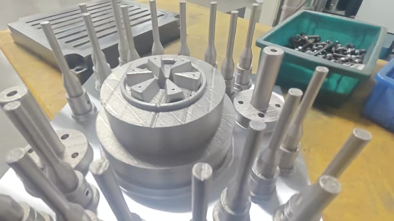
3. How Conformal Cooling Works
Conformal cooling channels are manufactured using Laser Powder Bed Fusion (LPBF) metal 3D printing — a process that builds metal mould inserts layer by layer from steel powder. Unlike drilling, LPBF can create channels that follow any arbitrary 3D path.
The conformal cooling channel is designed to run parallel to the mould cavity surface at a constant distance of 2–4mm. Instead of straight lines, the channel spirals, curves, or zigzags to follow the part contour — maintaining a constant distance from the mould surface regardless of how complex the geometry.
The Key Advantage: Temperature Uniformity
| Parameter | Conventional Cooling | Conformal Cooling |
|---|---|---|
| Mould surface temperature uniformity | ±20–45°C variation | ±2–5°C variation |
| Time to solidification (typical engineering resin) | 8–15 seconds | 4–8 seconds |
| Warpage on complex geometry | 0.3–1.5mm/100mm | <0.1mm/100mm |
| Cycle time reduction vs conventional | Baseline | 20–55% |
| Scrap rate (warpage/dimensional reject) | 1–5% | 0.1–0.5% |
4. Performance Data: What to Expect
Based on production data from over 200 conformal cooling insert deployments, the following performance benchmarks have been measured:
Interior Panel Components
Closures & Containers
Device & Diagnostic Components
Enclosures & Connectors
5. Design Requirements for Conformal Cooling
To design and manufacture effective conformal cooling channels, the following parameters must be specified:
| Parameter | Standard Value | Why It Matters |
|---|---|---|
| Channel diameter (D) | 8–12mm | Sized for turbulent flow (Re > 10,000) at practical pump pressures (2–5 bar) |
| Channel-to-surface distance (W) | 1.5–2×D from surface | Too close = structural failure; too far = reduced heat transfer effectiveness |
| Channel pitch (P) | 2–3×D | Closer spacing = better uniformity; wider spacing = easier manufacturing |
| Minimum bend radius (R) | ≥1.5×D | Tighter bends cause excessive pressure drop and flow separation |
| Target coolant temperature | 15–35°C (chiller water) | Lower = faster cooling but condensation risk; balance for your shop environment |
| Target flow rate per circuit | 8–15 L/min (Re > 10,000) | Turbulent flow is essential — laminar flow dramatically reduces heat transfer coefficient |
Geometry Requirements for Your Mould Insert
To receive a conformal cooling quote, we need:
- Insert geometry as STEP file (SolidWorks, CATIA, NX, Creo, or Fusion 360 export)
- Cooling circuit inlet/outlet positions (or leave to our engineers)
- Resin type (affects thermal analysis — PP, PA, PC, ABS etc.)
- Target cycle time and current cycle time
- Annual production volume (for ROI calculation)
- Maximum injection pressure (determines material selection)
6. Material Selection: 420SS vs 18Ni300 vs CuCrZr
| Material | Hardness | Thermal Conductivity | Price Tier | Best For |
|---|---|---|---|---|
| 420 Stainless Steel | 48–52 HRC (after HT) | 24–28 W/m·K | $$ | Standard moulding applications, cost-sensitive projects, ≤1,200 bar injection pressure |
| 18Ni300 Maraging Steel | 52–56 HRC (after aging) | 25–30 W/m·K | $$$ | High-cycle moulding (>500K shots/year), engineering resins (PC, PA-GF, POM), demanding dimensional tolerances |
| CuCrZr Copper Alloy | 85–95 HRB | 300–320 W/m·K | $$$$ | Maximum heat extraction where mechanical loads are low — packaging applications, lightly-loaded inserts. Not suitable for high-pressure moulding. |
For most UK and Australian injection moulding applications: 420 Stainless Steel for standard commodity moulding; 18Ni300 for automotive, medical, and precision technical moulding; CuCrZr only where cooling is the absolute priority and mechanical load is light.
7. ROI Calculation for UK & Australian Mould Shops
The financial case for conformal cooling is strongest where:
- Production volume is high (annual output >500,000 parts)
- Current cycle time is long (cooling-limited cycle >20 seconds)
- Part geometry is complex (curved, with ribs or bosses)
- Warpage or dimensional rejects are generating significant quality costs
UK Example: Automotive Fascia Clip (Tier 2 Supplier)
| Before | After Conformal Cooling | |
|---|---|---|
| Cycle time | 38 seconds | 24 seconds |
| Cavities | 4 | 4 |
| Parts/hour | 379 | 600 |
| Annual output (2-shift) | 2.28M parts | 3.6M parts |
| Insert cost (420SS, UK landed) | — | ~£2,400 |
| Payback period | — | 3–5 weeks |
Australian Example: Packaging Cap (FMCG)
| Before | After Conformal Cooling | |
|---|---|---|
| Cycle time | 14 seconds | 9 seconds |
| Cavities | 8 | 8 |
| Parts/hour | 2,057 | 3,200 |
| Insert cost (420SS, AU landed) | — | ~A$3,200 |
| Payback period | — | 2–4 weeks |
8. Delivery to UK & Australia
United Kingdom
- DHL Express from Ningbo: 3–4 days to London, Birmingham, Manchester
- Total lead time: 10–14 days from order confirmation
- UK import duty: 1.7–2.7% (UK Global Tariff on mould components)
- UK VAT (20%) recoverable as input VAT for VAT-registered businesses
- Invoice in GBP available on request
Australia
- DHL Express from Ningbo: 3–5 days to Sydney, Melbourne, Brisbane
- Total lead time: 10–14 days from order confirmation
- Import duty: 0% under ChAFTA (China–Australia FTA)
- 10% GST recoverable as ITC for GST-registered businesses
- Invoice in AUD available on request
9. Getting a Quote
To get a conformal cooling quote, you need to provide:
- Insert STEP file (or 2D drawing with key dimensions)
- Moulding resin type (PP, PA6, PC, ABS, etc.)
- Current cycle time and target cycle time
- Annual production volume
- Maximum injection pressure (for material selection)
We return within 24 hours with:
- Conformal channel layout drawing
- Predicted cycle time saving (±10%)
- Material recommendation with rationale
- Firm price in GBP, AUD, or USD
- Lead time confirmation
Request a Free Conformal Cooling Quote
Send us your mould insert drawing and we'll design the conformal channels and quote within 24 hours. UK delivery 10–14 days. Australia delivery 10–14 days.
View Conformal Cooling Service → WhatsApp for Quick Quote