Conformal Cooling & 3D Printing: Which Process, Which Material, and What It Actually Costs
- Why 3D printing is not just the best — it's the only way to manufacture conformal cooling channels
- SLM vs. DMLS vs. binder jetting: which process is right for mold inserts
- Step-by-step manufacturing workflow from CAD file to finished insert
- Material selection guide: 420 steel vs. 18Ni300 vs. CuCrZr — when to use each
- Design-for-3D-printing rules that most engineers get wrong
- Real cost breakdown: what a 3D printed conformal cooling insert actually costs
Table of Contents
- Why 3D Printing Is the Only Option
- SLM vs. DMLS vs. Binder Jetting: Which Process for Mold Inserts?
- The SLM Manufacturing Process — Step by Step
- Material Selection: 420 SS vs. 18Ni300 vs. CuCrZr
- Design-for-3D-Printing Rules for Conformal Channels
- Real Project: 3D Printed Conformal vs. Drilled Conventional
- What Does It Cost? Real Price Ranges
- FAQ
Why 3D Printing Is the Only Option for Conformal Cooling
The phrase "conformal cooling" is sometimes used loosely to mean "better cooling." But in manufacturing terms, it has a precise meaning: cooling channels that conform to — follow the surface of — the mold cavity at a constant offset distance.
That geometric requirement immediately rules out all conventional subtractive manufacturing methods:
| Manufacturing Method | Can Make Conformal Channels? | Why Not |
|---|---|---|
| Gun drilling | ✗ No | Only straight-line paths possible; cannot bend around geometry |
| CNC milling | ✗ No | Tool access requires open geometry; cannot machine enclosed internal channels |
| EDM (wire or sinker) | ✗ No | Requires electrode access; cannot create fully enclosed 3D curved channels |
| Baffles / bubblers | ✗ Workaround | Extends straight channels into cores, but cannot truly follow complex surfaces |
| Vacuum brazing (split mold) | ⚠ Partial | Channels milled in two halves and brazed; limited to near-planar geometries, bonding reliability concerns |
| SLM / DMLS metal 3D printing | ✓ Yes | Builds geometry layer by layer; channels created during print with no access constraints |
The physics of why this matters: a conformal channel maintains a constant offset of 8–15mm from the mold surface, regardless of how curved or deep the part geometry is. A drilled channel, by contrast, can only approach within ~25–30mm of complex surfaces before structural risk becomes unacceptable — and often cannot reach deep core tips at all.
SLM vs. DMLS vs. Binder Jetting: Which Process for Mold Inserts?
Several metal additive manufacturing processes can create internal channels. Not all are suitable for injection mold inserts that must withstand 50–150 MPa injection pressure, 50+ HRC hardness, and millions of cycles. Here's the comparison:
| Process | Density | Achievable Hardness | Surface Finish (as-built) | Suitable for Mold Inserts? |
|---|---|---|---|---|
| SLM (Selective Laser Melting) | 99.5–100% | Up to 54 HRC (after HT) | Ra 4–8 μm | ✓ Best choice |
| DMLS (Direct Metal Laser Sintering) | 95–99% | Up to 52 HRC (after HT) | Ra 4–10 μm | ✓ Excellent |
| EBM (Electron Beam Melting) | 99%+ | Up to 35 HRC (Ti alloys) | Ra 25–35 μm (rough) | ✗ Too rough, limited materials for molds |
| Binder Jetting + sintering | 96–98% | Up to 45 HRC | Ra 3–6 μm | ⚠ Limited — shrinkage control challenging for precision molds |
| DED (Directed Energy Deposition) | 99%+ | Up to 50 HRC | Ra 10–30 μm (very rough) | ✗ Poor for fine channels; mainly for repair/cladding |
SLM (Selective Laser Melting)
- Full melt — near 100% density
- Best mechanical properties
- Highest pressure integrity for channels
- Available in 420 SS, 18Ni300, CuCrZr
- Typical build rate: 5–20 cm³/hr
- Our primary process at MouldNova
DMLS (Direct Metal Laser Sintering)
- Sintering (partial melt) — 95–99% density
- Slightly lower strength than SLM at same material
- Wider equipment availability globally
- Available in similar material range
- In practice: SLM vs DMLS results nearly identical
- Industry often uses terms interchangeably
The SLM Manufacturing Process — Step by Step
Understanding the full manufacturing chain helps you specify correctly, avoid surprises, and communicate accurately with your supplier. Here's exactly what happens between your CAD file and a finished 3D printed conformal insert:
Design Review & DFM (Design for Manufacturing)
Channel routing is checked for: minimum wall thickness, bend radius compliance, support structure requirements, and powder removal path. Channels with no exit for loose powder must be redesigned — trapped powder causes hot spots and blockages. Critical: every conformal channel needs a clear powder evacuation route.
1–2 working daysSupport Structure & Build Orientation
The insert is oriented in the build chamber to minimize supports inside channels (supports inside a cooling channel cannot be removed). Overhangs >45° require supports; channel geometry is designed to avoid this. Build orientation also affects surface finish on critical mating faces.
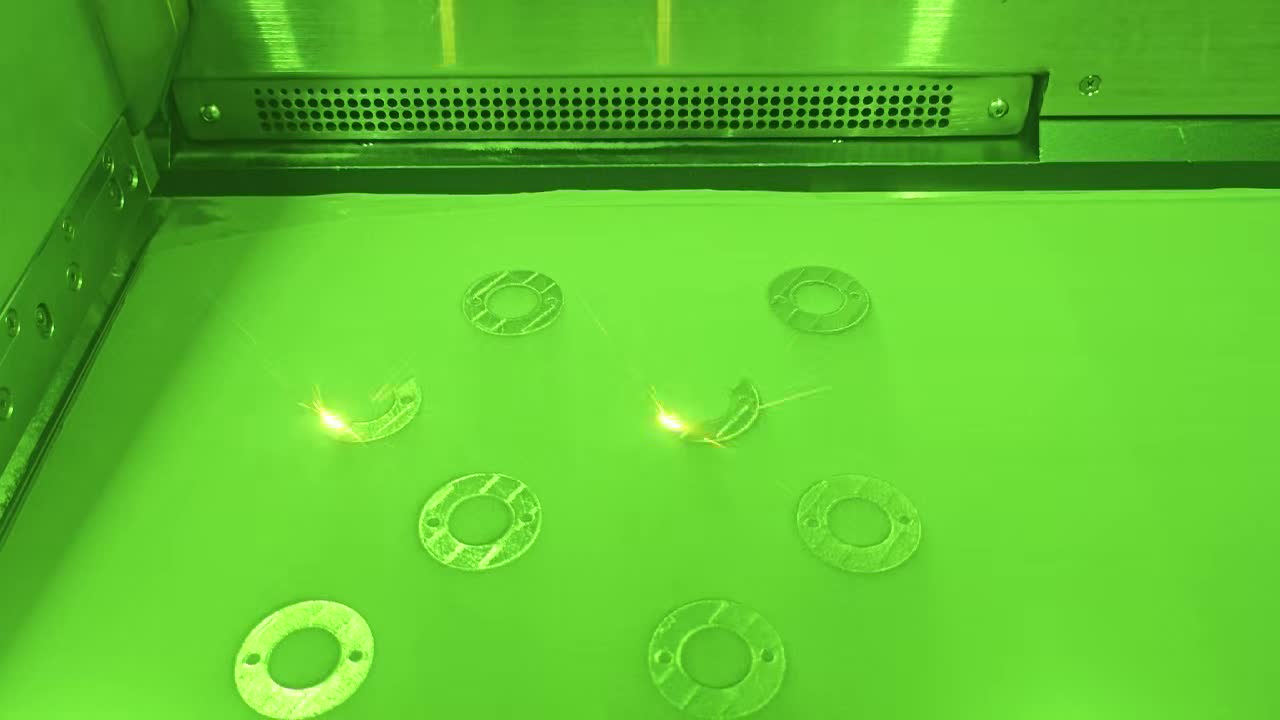
4–8 hours (engineer time)SLM Printing
Layer thickness: 30–60 μm (finer = smoother surface, longer build time). Laser power: 200–400W depending on material. Build atmosphere: inert argon gas to prevent oxidation. Typical print time for a 150×150×100mm insert: 18–36 hours. Multiple inserts are nested in one build to reduce cost per part.
1–3 days (print time)Stress Relief Heat Treatment
SLM-printed parts have high residual stress from rapid heating/cooling of the laser. Parts are stress-relieved at 450–600°C before removal from build plate. Skipping this step causes distortion during CNC machining. This is a non-negotiable step — ask any supplier whether they do it.
1 dayPowder Removal & Channel Cleaning
Loose powder is blown and vibrated out of all channels. Internal channel inspection via borescope camera confirms channels are clear. Ultrasonic cleaning removes residual powder from channel walls. Blocked channels = dead zones in cooling = hot spots in the mold.
4–8 hoursCNC Finish Machining
All mating surfaces (parting line, ejector pin holes, guide pin bores) are machined to drawing tolerance. The as-printed surface Ra 4–8 μm is only acceptable for non-mating areas. Mating surfaces are machined to ±0.05–0.1mm. This is where insert dimensional accuracy is finalized.
2–4 daysHardening Heat Treatment
420 SS: vacuum hardening at 1,020–1,050°C, quench, double temper at 200°C → 50–52 HRC. 18Ni300: age hardening at 490°C for 6 hours → 50–54 HRC (no quench needed — dimensional stability is excellent). CuCrZr: solution annealing + aging — achieves different hardness profile.
1–2 daysPolishing & Final Inspection
Cavity surface polished to required specification: texture mold (VDI standard), polished mold (SPI B1–A1), or technical surface. CMM dimensional inspection, hardness testing, channel pressure test at 1.5× operating pressure, and photography for delivery report.
1–3 daysWant to know the lead time and cost for your specific insert?
Share your STEP file and mold drawing. We'll quote within 24 hours with a full breakdown: print time, material, post-processing, and delivery.
Material Selection: 420 SS vs. 18Ni300 vs. CuCrZr
The choice of print material is the single biggest factor in both cost and performance of a conformal cooling insert. Here's the decision framework we use across 13 industries of production experience:
| Property | 420 Stainless Steel | 18Ni300 (Maraging Steel) | CuCrZr Copper Alloy |
|---|---|---|---|
| Hardness after HT | 50–52 HRC | 50–54 HRC | ~28–32 HRC |
| Thermal conductivity | ~24 W/m·K | ~25 W/m·K | ~320 W/m·K |
| Yield strength | ~1,500 MPa | ~1,900–2,000 MPa | ~500–600 MPa |
| Corrosion resistance | Good (stainless) | Moderate (requires coating for corrosive plastics) | Good |
| Wear resistance | Good | Excellent | Poor — not for abrasive materials |
| Relative cost | $ | $$ | $$$ |
| Best application | General purpose: most injection molds | High-cavitation, high-pressure, long-run molds | Targeted inserts: deep cores, hot-runner zones, max heat extraction |
When to choose 420 Stainless Steel
420 SS is the default choice for 70–80% of conformal cooling applications. It delivers 50–52 HRC hardness (equivalent to conventional mold steel), excellent corrosion resistance for processing PVC, flame-retardant ABS, or other corrosive plastics, and the lowest cost of the three options. If you're not running a specialized application, start here.
When to upgrade to 18Ni300 Maraging Steel
The 300-grade maraging steel provides ~30% higher yield strength than 420 SS and the highest hardness (54 HRC achievable). This matters for:
- High-cavitation molds (8+ cavities) where clamping and injection forces are distributed across many small inserts
- Thin-wall inserts where wall thickness between channel and mold surface is below 6mm
- Molds processing glass-filled materials (PA66-GF30, PBT-GF) where abrasive wear is accelerated
- High-pressure injection applications (>150 MPa)
When to use CuCrZr Copper Alloy
CuCrZr's thermal conductivity (320 W/m·K) is 13× higher than steel. This makes it uniquely effective for specific locations: deep core tips where steel inserts still create a thermal bottleneck, hot-runner gate areas where rapid heat removal prevents gate drool, and thick sections where even conformal steel channels can't extract heat fast enough.
Design-for-3D-Printing Rules for Conformal Channels
3D printing enables geometry that machining cannot — but it has its own constraints. These rules are specific to conformal cooling channels in metal SLM printing, and violations are the most common cause of print failures or post-print surprises:
| Rule | Value | Why It Matters |
|---|---|---|
| Minimum channel diameter | 4mm (6mm recommended) | Channels <4mm are difficult to clear of sintered powder and risk blockage. See channel design rules |
| Maximum channel diameter | 12mm | Larger requires support structures inside channel — hard to remove |
| Self-supporting overhang angle | ≤45° from vertical | Overhangs >45° inside channels require supports that cannot be removed |
| Powder evacuation route | Required for every channel | Channels with no exit = trapped powder = blockage during pressure test |
| Minimum wall (channel to surface) | ≥1.0 × channel diameter | Thinner walls risk crack propagation under injection pressure cycling |
| Minimum wall (channel to channel) | ≥0.8 × channel diameter | Thinner inter-channel walls risk deformation during heat treatment |
| Transition from channel to fitting | Gradual taper, not abrupt step | Abrupt cross-section changes create turbulence dead zones — reduces cooling efficiency |
| Build orientation (channel axis) | Avoid horizontal channels parallel to build plate | Horizontal channels need internal supports — prefer channels running diagonally or vertically |
Optimal build orientation strategy
Build orientation affects three things: support structure amount (cost), surface finish on specific faces, and dimensional accuracy in Z vs. XY. General rules for mold inserts:
- Orient critical mating surfaces (parting line, guide pin bores) parallel to build plate where possible — XY accuracy is typically better than Z
- Orient channels so they run at 30–60° to the build plate — avoids fully horizontal sections while minimizing length in Z direction
- Minimize support on cavity surface — support witness marks require more post-machining time
Real Project: 3D Printed Conformal vs. Conventional Drilling
Core insert for structural door bracket — 52mm core depth, 8-cavity mold
The original conventionally drilled mold had straight channels that could not enter the core at all — a bubbler insert was used, but the bubbler created a single cooling point rather than distributed cooling. Core tip temperature ran 38°C hotter than the surrounding mold steel. This caused premature ejection warpage and a reject rate of 18%.
3D printed conformal approach: 18Ni300 maraging steel insert. Conformal channels wrapped around the core at 10mm offset from tip, spiraling from tip to base. Channel diameter 8mm, pitch 20mm. Total channel length per insert: 640mm. Build time: 28 hours. Post-processing: 6 working days.
What Does It Cost? Real Price Ranges
Most articles about conformal cooling 3D printing avoid discussing cost. Here is our actual pricing structure, which reflects the costs of SLM printing + full post-processing at our Ningbo facility. European and North American suppliers typically charge 2–3× these figures for equivalent inserts.
Small Insert — ≤100 × 100 × 80 mm (420 SS, standard conformal channel)
Medium Insert — 100–200 mm cube (18Ni300, complex conformal channel)
Large Insert — >200 mm cube (18Ni300 or 420 SS, multi-zone conformal)
For reference: a conventionally machined insert of equivalent size typically costs 40–60% less. The conformal cooling premium is recovered through cycle time savings. For a detailed breakdown, see our metal 3D printing cost guide. For a mold running 100,000+ shots/year, the payback period for this premium is typically 3–8 months.
Ready to Get a Quote for Your Conformal Cooling Insert?
Send your STEP file and mold drawing. We'll confirm the build approach, material recommendation, and quote with full cost breakdown within 24 hours.
Frequently Asked Questions
Why is metal 3D printing the only way to make true conformal cooling channels?
What is the difference between SLM and DMLS for conformal cooling?
Which material should I use for 3D printed conformal cooling inserts?
How long does it take to 3D print a conformal cooling mold insert?
What does a 3D printed conformal cooling mold insert cost?
Related Articles & Pages
- Conformal Cooling in Injection Molding: Cycle Time, Cost & Real Factory Data
- Conformal Cooling vs. Conventional Cooling: Full Comparison
- What Is Conformal Cooling? Complete Technical Guide
- Our 3D Printed Mold Insert Service — SLM Manufacturing
- Metal 3D Printing Service — Materials & Capabilities
- Conformal Cooling Insert Service — Specs & Lead Times