Overview — Why Troubleshooting Conformal Cooling Differs from Conventional Cooling
Conformal cooling channels follow the three-dimensional contour of the mold cavity surface, enabling heat extraction that is geometrically impossible with straight-drilled conventional circuits. When these channels perform as designed, the results are well-documented: cycle time reductions of 20–40%, warpage reductions of 40–70%, and scrap rates cut to below 2%. However, the same design freedom that enables superior performance also introduces failure modes that do not exist with conventional straight-drilled circuits.
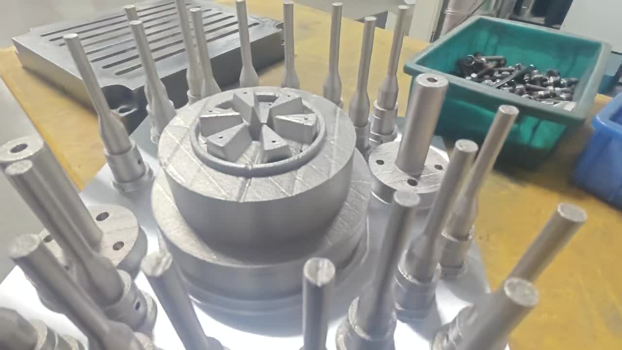
Conformal cooling inserts produced by selective laser melting (SLM) contain internal channel geometries that cannot be inspected visually after manufacture. Channels run in three dimensions with varying diameter, curvature, and wall thickness. Flow distribution across multiple parallel branches requires balancing that conventional circuits — with their predictable straight-line geometry — rarely need. When problems arise, the diagnostic approach must be systematic, starting from the most probable cause based on the specific symptom.
This guide covers 12 problems encountered in real conformal cooling production environments. Each entry follows a four-part structure: symptom, root cause, diagnostic method, and fix. A quick-reference table at the end consolidates all 12 for rapid field use.
Approximately 60% of conformal cooling production problems trace back to installation or process setup errors — not design or manufacturing defects in the insert itself. Always audit the installation and process parameters before concluding the insert is defective.
The 12 Problems: Symptom, Cause, Diagnosis & Fix
Upsize supply and return connections to match the channel inlet diameter. Replace restrictive quick-disconnect fittings with full-bore ball valve connections. Verify filter screens are clean — replace if blocked. Check pump condition. If flow is correct at the manifold but low in the circuit, the channel itself may be partially blocked (see Problem 4).
Flush the circuit with a citric acid or EDTA descaling solution to remove deposits. If deposits are cleared but pressure drop remains high, the channel geometry needs redesign — increase bore diameter or split long circuits into parallel shorter sub-circuits. For multi-circuit imbalance, install flow-balancing valves on individual branches, or hydraulically redesign circuits to equal length (see the conformal cooling channel design guide for balanced manifold configurations).
Replace O-rings with EPDM or Viton material rated for the coolant chemistry in use. Verify O-ring groove dimensions against AS568 or BS1806 standards — groove depth must be 70–75% of O-ring cross-section diameter to prevent extrusion without over-compression. Apply PTFE thread tape plus liquid thread sealant on NPT connections. Conduct a nitrogen pressure test before returning the tool to production.
Flush circuit with 5% citric acid solution at 40°C for 2 hours; neutralize with baking soda solution; flush with clean deionized water. Refill with treated coolant (deionized or RO water, 10–15% corrosion inhibitor, 150 ppm biocide, pH 7.5–9.0). Install a 5-micron inline filter. Specify electropolished channel finish (Ra <3 μm) on new inserts to reduce nucleation sites. Implement a quarterly coolant testing and semi-annual chemical cleaning schedule.
Convert series circuits to parallel by adding a manifold that supplies each cavity circuit independently from a common header. Balance parallel branch flows using needle valves with inline flow meters on each branch. For standoff distance issues, this requires insert redesign — the channel centerline should be within 2.5–4x the channel diameter from the cavity surface, maintained consistently across all cavities.
Redesign the channel layout to increase coverage in the hot zone: reduce standoff distance to 1.5–2.5x channel diameter, reduce channel center-to-center spacing to 3x channel diameter. For boss and rib tip areas that cannot be reached by channels, specify conformal cooling pins or baffles integrated into the insert design. If the hot spot is in an adjacent steel section not covered by the insert, extend the retrofit scope to include that zone.
Raise coolant supply temperature above the dew point — typically to 18–22°C in a standard factory environment. Use a chiller-with-heater temperature control unit rather than a plain chiller; this allows precise setpoint control rather than simply minimizing coolant temperature. For humid environments (monsoon season in South Asian facilities, or coastal locations), install a shop dehumidification system that maintains relative humidity below 50%. Never seal condensation with grease or silicone — this causes surface quality failures and masks the underlying problem.
For fatigue cracks: redesign channel bends to minimum radius 1.5x channel diameter; specify minimum wall thickness 1.5 mm; implement a mold pre-heat protocol (reach operating temperature at 5°C/min maximum rate before applying full coolant flow). For material defects: require CT scan report and density certificate above 99.5% from your SLM supplier on every insert. Specify post-build solution annealing and aging heat treatment per the conformal cooling materials guide. A cracked insert cannot be welded and must be replaced.
If gate freeze-off is limiting pack time: optimize gate geometry — a smaller gate freezes faster, allowing shorter pack time (this is a mold design change, not a cooling change). If ejection is limiting: increase ejector plate speed, add ejector area to reduce sticking, or improve part draft angle on the core side. If mold open/close is limiting: optimize the clamp speed profile. If flow rate is below spec: correct the supply-side restriction (see Problem 1). For a comprehensive cycle time reduction methodology, address all phases simultaneously.
Apply conformal cooling to both cavity and core sides for symmetrical heat extraction. Optimize pack pressure profile to minimize packing-driven differential shrinkage — reduce peak pack pressure and increase pack time to allow gradual shrinkage. For fiber-filled resins, modify gate location and orientation to align fiber direction with the desired structural axis. If ejector marks or sticking are causing ejection distortion, add ejectors or a stripper ring to distribute ejection force. Implement a post-mold fixture to hold parts during cooling if residual warpage is small (less than 0.3 mm).
Raise coolant temperature to keep mold surface above the minimum recommended mold temperature for the resin — this is especially important for ABS, PC, and PC/ABS which require mold temperatures of 60–90°C for adequate surface replication. Polish the insert cavity surface to match the finish specification of adjacent mold steel (specify polishing sequence Ra 0.4, 0.2, 0.1 μm as required). Eliminate condensation using the method in Problem 7. If the insert material causes a color or reflectivity difference in the cavity, apply a thin chrome or TiN PVD coating to normalize the surface.
If flow is too high: reduce flow rate using a needle valve until delta-T reaches 4–8°C, which indicates effective heat utilization. This also reduces pump energy consumption. If thermal isolation is the issue: disassemble the insert and inspect the mating surfaces for gaps, corrosion, or contamination. Apply thermally conductive paste at the insert-to-mold interface if specified by the insert manufacturer. If SLM channel walls show a sintered powder layer reducing thermal conductivity, remove the insert and clean internally with chemical flushing plus ultrasonic agitation. Confirm with the manufacturer that heat treatment protocols were followed — under-aged maraging steel has lower thermal conductivity than fully heat-treated material.
Quick-Reference Diagnostic Table
Use this table for rapid field diagnosis. Start with the most prominent symptom and follow to the most likely cause and first-step fix.
| # | Primary Symptom | Most Likely Cause | First Diagnostic Step | First Fix |
|---|---|---|---|---|
| 1 | Flow rate below spec | Restrictive supply fittings or closed valve | Measure flow at each section with inline meter | Upsize connections; open valves fully |
| 2 | Pressure drop too high | Channel blockage or undersized bore | Pressure gauge at inlet and outlet | Flush with citric acid; redesign if geometric |
| 3 | Coolant leaks at seals | O-ring material incompatibility or wrong size | Nitrogen pressure test; UV dye inspection | Replace with EPDM/Viton O-rings; re-test |
| 4 | Progressive flow decline | Scale or corrosion deposit buildup | Coolant TDS and pH test; sample analysis | Citric acid flush; implement coolant treatment program |
| 5 | Cavity-to-cavity temperature variation | Series wiring or flow imbalance | Thermocouple at each cavity circuit outlet | Convert to parallel; add balancing valves |
| 6 | Hot spots persist after retrofit | Inadequate channel coverage in hot zone | Thermal image overlaid on channel layout | Redesign channels; reduce standoff and spacing |
| 7 | Condensation on mold surface | Coolant temp below dew point | Measure dew point; measure mold surface temp | Raise coolant setpoint above dew point |
| 8 | Insert cracking in production | Thermal fatigue or material defect | Fracture surface microscopy; review density cert | Redesign bend radius; specify pre-heat protocol |
| 9 | Cycle time not improving | Another phase now dominates the cycle | Machine controller cycle breakdown report | Optimize bottleneck phase (pack, eject, or open) |
| 10 | Warpage not reduced | Cooling asymmetry or non-cooling warpage source | Moldflow warpage analysis by source | Cool both cavity and core; optimize pack profile |
| 11 | Surface quality degraded | Mold surface too cold or condensation pitting | Check mold temp vs. resin spec; inspect for condensation | Raise coolant temp; polish insert cavity surface |
| 12 | Coolant delta-T <2°C | Flow too high or thermal isolation at interface | Calculate theoretical vs. actual heat removal | Reduce flow to target 4–8°C delta-T; inspect interface |
Preventive Maintenance: Avoiding Problems Before They Start
The majority of the 12 problems above are preventable with a structured maintenance program. Most conformal cooling production problems develop over time rather than appearing suddenly at startup, which means a consistent monitoring protocol provides early warning before problems escalate to downtime or scrap events.
Recommended monitoring schedule:
- Each shift: Record coolant inlet and outlet temperature and flow rate for each circuit. Note any deviation from the baseline established at commissioning.
- Weekly: Measure coolant pH and conductivity. Record and trend. Replace coolant if pH drifts outside 7.5–9.0 or conductivity rises above 500 μS/cm.
- Monthly: Infrared thermal scan of mold surface at steady state. Compare against commissioning baseline thermal map. Any new hot spot indicates a change in cooling performance requiring investigation.
- Every 6 months: Full chemical flush of all cooling circuits per the conformal cooling line cleaning guide. Nitrogen pressure test to verify seal integrity. Inspect all O-rings and replace proactively.
- Annually: Submit coolant sample for full laboratory analysis. Inspect insert cavity surface for erosion or pitting. Review insert density and materials documentation for the production record file.
A conformal cooling insert that is properly maintained has a service life of 500,000 to 2,000,000 shots depending on material, resin, and process conditions. Neglected coolant chemistry and delayed seal replacement are the two factors most likely to shorten insert life below this range.
When to Call the Insert Manufacturer
Most of the 12 problems in this guide can be diagnosed and resolved on-site using the methods described. However, certain conditions warrant direct engagement with the insert manufacturer:
- Insert cracking confirmed as material defect — fracture analysis showing intergranular failure or inclusions visible at the fracture origin indicates a manufacturing quality issue requiring supplier corrective action.
- Persistent hot spots that cannot be resolved by flow optimization — if thermal imaging consistently shows inadequate coverage in a specific zone after all process adjustments, the channel layout requires redesign. Share the thermal map with your supplier for analysis.
- Coolant delta-T persistently near zero at correct flow rate — this indicates possible delamination of the insert from the mold base or a thermal conduction path that was not achieved during manufacture. A CT scan ordered through the manufacturer can confirm internal condition.
- Pressure drop increasing faster than expected between cleans — accelerated scale buildup may indicate that the internal surface finish is rougher than specified, or that the channel geometry includes dead zones where stagnant coolant deposits scale. The manufacturer can review the as-built CT scan against the design intent.
For new insert orders following a troubleshooting exercise, consider requesting: (1) electropolished internal channel finish (Ra <3 μm) to reduce scale nucleation, (2) full CT scan report confirming channel dimensions and wall thickness throughout the build, (3) helium leak test at 1.5x working pressure, and (4) documented heat treatment records showing aging temperature and duration. These requirements add marginally to cost but prevent the majority of the problems listed in this guide. See the conformal cooling design guide for specification language you can include in a purchase order.
FAQ — Conformal Cooling Troubleshooting
Excessive pressure drop is almost always caused by one of three root causes: channel diameter is too small relative to circuit length, partial blockage from scale or sintered powder debris, or circuit length is too long without intermediate manifold breaks. Diagnose by measuring inlet vs. outlet pressure with calibrated gauges. If delta-P exceeds design specification by more than 20%, flush with citric acid solution to clear deposits first. If pressure drop remains high after flushing, the channel geometry is the issue — redesign with larger bore or parallel sub-circuits.
Use an infrared thermal camera on the mold surface during production to map the hot zone precisely. Overlay the thermal map against your channel layout drawing at the same scale. If the hot spot falls between channels or in an area with large channel-to-surface standoff distance, the channel layout needs redesign. Flow balancing valves on parallel branches can redirect more flow toward the hot zone as a first step. If the hot spot is in an area not covered by the insert at all, the retrofit scope needs to be extended.
Condensation forms when the mold surface temperature drops below the dew point of the ambient air. This occurs when coolant temperature is set too low — a common mistake when operators try to maximize cooling rate. Measure shop dew point and compare with actual mold surface temperature. Raise the coolant supply temperature setpoint above the dew point (typically 18–22°C for a 25°C factory environment at 60% RH). For permanently humid environments, install shop dehumidification. Never mask condensation with sealant — this causes surface quality failures.
Pull a cycle breakdown report from the machine controller and identify which phase dominates the total cycle time. If cooling time decreased as predicted but total cycle did not, another phase (pack, mold open, or ejection) is now the bottleneck. Verify actual coolant flow rate against design specification with an inline flow meter — many systems run 30 to 50 percent below design flow due to supply-side restrictions. If flow is correct and cooling is no longer the bottleneck, focus optimization on the next longest phase.
Design channels with minimum bend radius of 1.5x the channel diameter and minimum wall thickness of 1.5 mm. Specify maraging steel MS1 or H13 with documented density above 99.5 percent from the manufacturer. Implement a mold pre-heat protocol that brings the insert to operating temperature gradually (5°C per minute maximum) rather than applying full cold coolant flow to a room-temperature mold. Require a documented heat treatment record from the supplier confirming proper solution annealing and aging. If cracking occurs, examine the fracture surface under magnification to distinguish thermal fatigue from material defects before deciding on corrective action.
Related Articles
- Conformal Cooling Channel Design — Diameter, Spacing, Standoff, and Layout Principles
- How to Clean Conformal Cooling Lines — Chemical Flush Procedure and Maintenance Schedule
- Conformal Cooling Materials — MS1, H13, and Maraging Steel Compared
- Conformal Cooling Design Guide — From Part Geometry to Channel Layout
- Conformal Cooling Simulation — Moldflow and Moldex3D Workflow for Thermal Validation
- Conformal Cooling Retrofit — Adding Conformal Channels to Existing Molds
- Cycle Time Reduction with Conformal Cooling — How to Measure and Maximize the Gain
- Conformal Cooling Inserts — MouldNova Service Details & Specifications