1. What the Conformal Cooling Process Is
The conformal cooling process is the complete manufacturing and integration workflow that transforms a conventional injection mold insert — with straight-drilled cooling channels — into a 3D-printed metal insert whose cooling channels follow the exact contour of the mold cavity surface at a constant offset distance of 2–5mm.
The process spans two distinct phases:
- Engineering phase (Steps 1–2): Thermal simulation to identify where heat is concentrated and design work to define channel geometry, layout, and hydraulic parameters.
- Manufacturing and qualification phase (Steps 3–7): LPBF printing, powder removal and post-processing, incoming quality inspection, fitting into the mold base, and commissioned production.
Getting any single step wrong can negate the thermal benefits or — in the worst case — result in a blocked or leaking insert reaching the press. This guide documents the full process as practiced at MouldNova, including the specific acceptance criteria we use at each stage.
2. Step 1 — Thermal Mapping: Finding the Hot Spots
You cannot design effective conformal cooling without first knowing where heat accumulates in the mold cavity. Thermal mapping is not an optional first step — it is the foundation that determines channel placement, diameter, and spacing for every subsequent decision.
Simulation Software
Thermal mapping is performed using injection molding process simulation software. The two industry-standard tools are:
- Autodesk Moldflow Insight — the most widely adopted tool globally; used by MouldNova for all standard analyses. 3D FEM (Finite Element Method) analysis provides full volumetric temperature distribution, not just surface results.
- CoreTech Moldex3D — preferred in East Asian supply chains; broadly equivalent capability to Moldflow for cooling analysis.
Key Outputs of the Thermal Map
A thermal mapping analysis produces four critical outputs that directly drive channel design:
- ΔT across the cavity surface — the temperature differential from hottest to coolest point on the mold cavity wall at end-of-cooling. For conventional cooling, ΔT is typically 15–40°C; the conformal cooling target is ΔT ≤ 5°C.
- Time-to-ejection temperature map — which regions of the part are still above ejection temperature when the rest of the part is ready. These are the cycle-time-limiting zones.
- Cooling time baseline — the total cooling time required with the existing (or hypothetical baseline) cooling circuit. This is the benchmark against which the conformal design is evaluated.
- Warpage prediction — differential cooling-induced warpage in mm, which quantifies the quality improvement opportunity.
Interpreting the Results
Hot spots — regions where the mold surface temperature exceeds the average cavity temperature by more than 8–10°C — are the priority targets for conformal channels. Common hot spot locations include:
- Deep ribs and bosses (straight drill bits cannot reach without intersecting each other)
- The geometric center of large flat surfaces
- Sharp corners and transitions where metal volume is low and heat accumulates
- Cores with small cross-section that cannot accommodate sufficient conventional channels
3. Step 2 — Channel Design: Geometry, Hydraulics, and Parameters
With the thermal map in hand, the channel design stage translates heat distribution data into a fully defined 3D channel geometry that can be printed by LPBF and will achieve the target thermal performance.
Core Design Parameters
Every conformal cooling channel is defined by four geometric parameters, commonly abbreviated D/W/P/R:
- D — Channel diameter: The internal hydraulic diameter of the cooling channel. Standard range: 3–8mm for injection mold inserts. Minimum achievable by LPBF: 2mm circular cross-section.
- W — Wall thickness: The distance from the outer wall of the channel to the nearest surface — either the mold cavity surface or an adjacent channel. Minimum: 1.5mm from channel outer wall to cavity surface; 1.0mm between adjacent channel walls.
- P — Pitch: The center-to-center spacing between adjacent parallel channel runs. Typically 2.5–3× the channel diameter for optimal thermal uniformity.
- R — Radius of curvature: The minimum bend radius at channel turns. LPBF-printed channels should maintain R ≥ 1.5× D to avoid flow separation and powder trapping. Tighter bends are possible but require special depowdering attention.
Channel Geometry Selection
Three primary channel geometries are used in conformal cooling design, selected based on part shape and the thermal map results:
| Geometry | Best For | Advantages | Limitations |
|---|---|---|---|
| Conformal Serpentine (Straight-Conform) | Flat-to-moderately-curved surfaces | Uniform flow distribution; easy flow balance; lowest pressure drop | Less effective for complex 3D contours; may require multiple circuits |
| Conformal Spiral (Baffle-Conform) | Cylindrical cores and pins | Even cooling of cylindrical geometry; natural depowdering path | Higher pressure drop than serpentine; requires precise pitch control |
| Free-Form Conformal | Complex 3D geometries, deep draws | Maximum conformance to cavity shape; lowest ΔT achievable | More complex design; requires CFD validation; higher depowdering challenge |
Reynolds Number Target
The most important hydraulic parameter in channel design is the Reynolds number (Re) — the dimensionless ratio of inertial to viscous forces in the coolant flow, which determines whether flow is laminar or turbulent.
Turbulent flow (Re > 4,000) dramatically improves heat transfer at the channel wall. The target Reynolds number for conformal cooling channels is Re = 4,000–8,000 (turbulent regime). Above Re = 8,000, additional pressure drop yields diminishing heat transfer returns. Below Re = 4,000, you are in the transition zone; below 2,300 is fully laminar with substantially reduced heat transfer.
Re = (ρ × v × D) / μ
Where: ρ = coolant density (kg/m³), v = flow velocity (m/s), D = hydraulic diameter (m), μ = dynamic viscosity (Pa·s). For water at 20°C: ρ = 998 kg/m³, μ = 0.001 Pa·s. A 4mm diameter channel requires ~0.4 m/s flow velocity to achieve Re = 1,600 (laminar) and ~1.0 m/s for Re = 4,000 (turbulent onset).
Channel diameter and pump flow rate are co-designed to achieve the target Re. If the customer's coolant supply is limited (low-pressure mold temperature controller), a smaller channel diameter (3–4mm) requires lower absolute flow rate to achieve turbulent conditions, which is a key design lever.
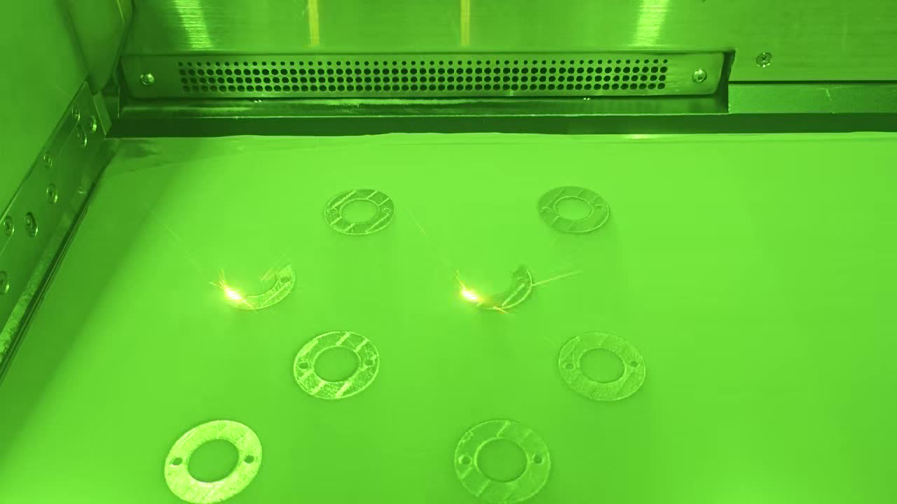
4. Step 3 — LPBF Printing: Materials, Parameters, and Build Strategy
Laser Powder Bed Fusion (LPBF) is the manufacturing process that makes conformal cooling channels physically possible. No other production manufacturing technology can produce the internal 3D channel geometries required at the precision and density needed for injection mold service.
Material Selection
Three materials cover the vast majority of conformal cooling insert applications. Material choice is made at the design stage and cannot be changed after printing begins:
| Material | As-Built Hardness | After Heat Treatment | Thermal Conductivity | Best Use Case |
|---|---|---|---|---|
| 420 Stainless Steel | 25–30 HRC | HRC 50–52 (HT at 1020°C) | 24–28 W/m·K | General-purpose injection molds. Lowest cost. Widest mold maker acceptance. |
| 18Ni300 Maraging Steel | 33–38 HRC | HRC 52–54 (aging at 490°C) | 25–30 W/m·K | High-cycle molds (>1M shots), high-pressure applications. Superior fatigue life. |
| CuCrZr Copper Alloy | 75–85 HRB | 85–95 HRB (aging) | ~320 W/m·K | Maximum heat extraction. Thin-wall parts, medical, optical. Use where loading is low. |
420 SS is the standard choice for new projects. It machines well, polishes to mirror finish, achieves production-grade hardness, and has the lowest material cost. 18Ni300 is specified when fatigue life or maximum hardness is the primary constraint — the aging treatment at 490°C is lower temperature than 420 SS austenitizing, which reduces distortion of complex geometries. CuCrZr is a specialist material: its thermal conductivity is more than 10× that of steel, but its lower hardness (comparable to soft brass) limits it to areas not subject to direct injection pressure or high sliding contact.
LPBF Process Parameters
Critical build parameters that affect internal channel quality:
- Layer thickness: 30–50μm. Thinner layers (30μm) improve surface finish on channel walls and reduce the risk of unmelted powder bridging small-diameter channels. Thicker layers (50μm) reduce build time by ~40% and are used for larger inserts where channel diameter is ≥5mm.
- Build volume: Typical LPBF systems used for mold inserts are 250×250×300mm. Inserts up to this size are printed in a single build. Larger molds require split inserts joined by CNC-machined mating faces.
- Atmosphere: Argon or nitrogen inert atmosphere throughout the build. Oxygen content monitored and maintained below 500 ppm to prevent oxidation of melt pool.
- Build orientation: Channels oriented >45° from the build plate are self-supporting and require no internal support material. Channels running more horizontally require careful support strategy — external supports on the underside of the build, with no supports inside channel bores.
Support Strategy for Internal Channels
The most important build preparation decision is support strategy. The key rule: never place support structures inside a cooling channel. Internal supports cannot be removed after printing and will permanently restrict flow or trap powder. Channel routing must ensure all channel runs are either self-supporting (≥45° angle) or use a down-skin contour scan strategy to bridge horizontal spans up to ~8mm without support. For channels that unavoidably run horizontal, an elliptical cross-section (taller than wide) is used: the ellipse's upper arc is self-supporting while maintaining equivalent hydraulic diameter to a circular channel.
5. Step 4 — Post-Processing: Depowdering, Heat Treatment, and Finish Machining
A freshly printed LPBF insert is not a finished mold component. Post-processing is as critical as printing itself — a poorly depowdered insert will have blocked or partially blocked channels that cannot be cleared after heat treatment.
Depowdering Protocol (7 Steps)
MouldNova uses a seven-step depowdering protocol for all conformal cooling inserts:
- Initial manual extraction — the insert is removed from the build chamber with channels oriented downward. Loose powder from main channel bores is extracted by gravity and compressed air purge before the insert reaches room temperature.
- Ultrasonic agitation — the insert is submerged in an ultrasonic cleaning bath (40 kHz, 30 minutes) to dislodge powder from channel walls, particularly at bends where powder compacts under build plate vibration.
- High-velocity flush (forward pass) — pressurized water at 8–10 bar is pumped through all channel inlets to outlet. Flow rate and pressure are logged. Any circuit showing >20% flow deficit vs. calculated is flagged for repeat ultrasonic treatment.
- High-velocity flush (reverse pass) — coolant direction reversed to dislodge powder trapped at channel bends. Flush continued until effluent runs clear with no visible particulate.
- Borescope inspection — a 2mm flexible borescope is passed through all accessible channel runs to visually confirm walls are clean and no powder bridges remain.
- Citric acid passivation — for 420 SS and 18Ni300 inserts, a citric acid passivation treatment (4% citric acid solution, 60°C, 30 minutes per ASTM A967) is applied to all wetted internal surfaces to remove free iron, improve corrosion resistance of channel walls, and reduce the risk of rust deposits contaminating the customer's coolant circuit.
- Final air purge and dry — compressed dry air at 6 bar purged through all circuits for 5 minutes to remove residual moisture before heat treatment.
Heat Treatment
Heat treatment transforms the as-built microstructure to production-ready hardness:
- 420 Stainless Steel: Austenitize at 1020°C in vacuum furnace, hold 60 minutes, gas quench to 70°C, temper at 200°C for 2 hours. Final hardness: HRC 50–52.
- 18Ni300 Maraging Steel: Solution anneal at 820°C for 1 hour (if required to relieve residual stress), then aging at 490°C for 6 hours, air cool. Final hardness: HRC 52–54. The low aging temperature minimizes geometric distortion — critical for inserts with tight tolerances on mating faces.
- CuCrZr: Solution treat at 980°C, water quench, age at 450°C for 3 hours. No vacuum furnace required; processed in air or inert atmosphere depending on surface finish requirements.
CNC Finish Machining
After heat treatment, all critical mating surfaces are CNC-machined to final dimensions:
- Parting faces and mold-base mating surfaces: tolerance H7/g6 or better; flatness ≤0.01mm
- O-ring grooves: machined to AS-568 standard dimensions, 2mm cross-section, NBR or FKM material as specified by customer. Groove surface finish Ra ≤ 1.6μm to ensure sealing.
- Coolant port threads: NPT 1/8" or BSP 1/8" as specified; cut with CNC tapping after surface machining to ensure concentricity
- Overall dimensional tolerance on insert body: ±0.05mm on critical dimensions; ±0.1mm on non-critical
6. Step 5 — Incoming Inspection: Three Non-Negotiable Tests
Before an insert ships, three quantitative tests are performed and documented. The results are included in the inspection certificate that ships with every insert.
Test 1: Hydrostatic Pressure Test
The insert is connected to a calibrated hydrostatic test rig. Each cooling circuit is pressurized to 1.5× the specified working pressure using water, with all other ports blocked. The pressure is held for a minimum of 10 minutes. Acceptance criteria: zero pressure drop across the hold period.
Standard working pressure for water cooling circuits: 6–8 bar. Standard test pressure: 9–12 bar. For high-pressure systems (10 bar working pressure), test pressure is 15 bar.
Any pressure drop — even 0.1 bar over 10 minutes — results in rejection, investigation, and re-manufacture. The most common causes of failure at this stage are incomplete fusion at sharp channel bends (a build parameter issue) and micro-cracks in thin walls between channels and exterior surfaces.
Test 2: Flow Rate Verification
Each circuit is tested at the design working pressure and the flow rate is measured. Acceptance criteria: measured flow rate within ±5% of the design target flow rate. A flow rate below target indicates residual channel restriction. A flow rate significantly above target may indicate an unintended channel breach or cross-connection between circuits.
Test 3: Surface Roughness on Sealing Faces
O-ring sealing faces and coolant port mating surfaces are checked with a contact profilometer. Acceptance criteria: Ra ≤ 3.2μm on sealing faces. This is the standard surface finish requirement for static O-ring seals. If Ra exceeds this threshold, the face is re-polished and re-tested.
7. Step 6 — Mold Integration: Fitting, Sealing, and Leak Test
A passed incoming inspection insert is ready for integration into the mold base. This step is typically performed by the mold maker at their facility, but MouldNova provides detailed installation instructions with every insert.
Fitting the Insert
Conformal cooling inserts are fitted to the mold base using the same approach as conventional inserts: interference or transition fit on locating diameters, with socket-head cap screws through clearance holes. The key difference is that all coolant circuit connections must be made before the insert is fully seated and clamped — it is not practical to re-seat an insert to fix a missed O-ring.
Installation sequence:
- Clean mold base pocket and insert body mating faces with isopropyl alcohol; remove any machining chips
- Install O-rings in all grooves — lightly lubricate with assembly lubricant compatible with the coolant (silicone-based for water; Molykote for cutting oils)
- Confirm O-ring cross-section sits proud of groove face by 15–20% of the cross-section diameter (standard compression for AS-568 2mm O-rings)
- Lower insert into pocket; connect coolant fittings (see below) before final seating
- Torque all cap screws to specification in cross pattern
Coolant Connection Options
Two connection systems are in common use. The correct choice depends on mold base design and customer preference:
- Push-to-connect fittings (e.g., SMC, Legris, Parker): Quick installation, reusable, rated to 10–15 bar. Preferred for molds that will be retooled frequently. Fitting body threaded into the insert coolant port; push-in tube connects on press.
- Threaded pipe connections (NPT / BSP): Higher pressure rating (up to 100 bar for hydraulic NPT fittings), more compact, no risk of tube disconnection. Standard for permanent production molds. NPT 1/8" most common in North America; BSP 1/8" standard in Europe, India, and Australia.
Leak Test at Mold Maker
After full integration, a final leak test is performed at the mold maker's bench before the mold goes to the press:
- Connect shop water supply (or mold temperature controller) to all cooling circuit inlets
- Pressurize to working pressure; inspect all O-ring interfaces and fittings for weeping
- Confirm flow from all outlets
- Hold for 5 minutes; confirm no pressure loss and no coolant at parting faces or mold base pockets
Any leak at an O-ring face is addressed by re-seating the insert (re-torquing cap screws) or replacing the O-ring. A leak through the insert body is extremely rare given the hydrostatic certificate but, if found, the insert is returned for investigation.
8. Step 7 — Commissioning: First-Shot Protocol and Cycle Time Measurement
Commissioning is the step where thermal performance is actually measured and compared to the Moldflow prediction. A structured first-shot protocol produces reliable data and catches any unexpected thermal behavior before high-volume production begins.
Pre-Shot Checklist
- Mold temperature controller set to target coolant supply temperature (typically 20–40°C for amorphous polymers; 40–80°C for semi-crystalline)
- All cooling circuit flows confirmed with rotameter readings at controller
- Mold soak: run mold through 20–30 dry cycles (no injection) to allow thermal equilibrium before measuring
- Infrared pyrometer or thermal camera ready for immediate mold surface temperature reading at ejection
Coolant Temperature Ramp-Up Procedure
Do not commission a new conformal cooling insert by jumping directly to production coolant temperature. Use this three-stage ramp-up:
- Stage 1 — Cold verification (15°C coolant): Run 10 shots at lowest coolant temperature. Purpose: confirm all channels are flowing, no thermal gradients from blocked circuits, no coolant leaks under thermal expansion.
- Stage 2 — Target temperature approach: Increase coolant temperature to target in 10°C increments, 5 shots per step. Monitor mold surface temperature at each step with thermal imaging.
- Stage 3 — Production conditions: Run at full production parameters. Record cooling time, total cycle time, and mold surface temperature uniformity (ΔT across cavity surface measured at ejection).
Cycle Time Measurement vs. Baseline
Cycle time improvement is measured by comparison to the baseline recorded in the Moldflow simulation and, where available, the historical conventional-cooled cycle time for the same mold or a comparable part.
Key measurement protocol:
- Minimum 50 consecutive shots at stable thermal equilibrium before recording cycle time
- Cooling time measured from injection gate closed to mold open signal
- Part temperature at ejection confirmed with IR pyrometer ± 3°C of target ejection temperature
- Warpage measured on 5 consecutive parts using CMM or optical measurement system
- Cycle time reduction reported as: (baseline cooling time − conformal cooling time) / baseline cooling time × 100%
9. Performance Data: Before and After by Part Type
The following table shows measured cycle time and quality improvements from MouldNova conformal cooling projects across four representative part categories. Conventional cooling baseline measured on same mold geometry before insert replacement.
| Part Type | Material | Conventional Cooling Time | Conformal Cooling Time | Cycle Time Reduction | ΔT Improvement | Warpage Improvement |
|---|---|---|---|---|---|---|
| Automotive Lens Housing | PC/ABS | 28.4 s | 16.1 s | −43% | 31°C → 4°C ΔT | 1.8mm → 0.3mm |
| PP Closure Cap (8-cavity) | PP (homo) | 11.2 s | 7.8 s | −30% | 22°C → 6°C ΔT | 0.4mm → 0.1mm |
| ABS Electronic Enclosure | ABS | 34.6 s | 21.2 s | −39% | 27°C → 5°C ΔT | 2.1mm → 0.4mm |
| Medical Syringe Barrel | PP (medical grade) | 19.8 s | 12.3 s | −38% | 18°C → 3°C ΔT | 0.6mm → 0.08mm |
Across these four cases, the average cooling time reduction is 37.5%, and temperature uniformity (ΔT) improved by an average factor of 6.4×. The medical syringe barrel achieved the best ΔT result (18°C → 3°C) due to the cylindrical geometry being highly amenable to conformal spiral channels with excellent surface area coverage.
10. Conformal Cooling Process vs. Conventional Drilling Process
| Parameter | Conformal Cooling Process | Conventional Drilling Process |
|---|---|---|
| Lead time (design to insert) | 10–14 business days | 2–5 business days |
| Insert cost (60×60×40mm) | $1,200–2,800 USD | $200–600 USD (machined only) |
| Upfront simulation cost | Included (free at MouldNova) | Rarely performed |
| Cooling time reduction vs. baseline | 20–55% | Baseline (0%) |
| Temperature uniformity (ΔT) | ±2–5°C across cavity | ±15–40°C across cavity |
| Design freedom | Full 3D freedom — any geometry | Constrained to straight drill paths |
| Warpage reduction | 60–90% reduction typical | Baseline |
| Deep core cooling capability | Excellent — channels designed into core | Limited — bubblers or baffles only |
| Repairability | Re-print if damaged; low EDM repair potential | Weld repair, re-drill — well-established |
| Typical ROI payback | 3–18 months at production volume | Immediate (no premium) |
| Quality documentation | ISO 9001, hydrostatic certificate, Moldflow report | Drawing compliance only |
The conformal cooling process has a clear cost and lead time premium over conventional drilling. The business case for conformal cooling is strongest when: production volumes are high (>100,000 shots/year), cooling is the dominant cycle time component, or part quality specifications (dimensional tolerance, warpage, sink marks) cannot be met with conventional cooling alone.
11. Common Process Failures and How to Avoid Them
These five failure modes account for the majority of conformal cooling process problems reported in the field:
Failure 1: Incomplete Depowdering — Channels Partially Blocked
Symptom: Flow rate at incoming inspection is 30–60% below design target. Thermal performance in production is below Moldflow prediction. May not be detected until parts show unexpected hot spots.
Root cause: Rushed or incomplete depowdering, especially in small-diameter (<3mm) channels or tight-radius bends where powder compacts. Common in suppliers who skip ultrasonic treatment or reverse-direction flushing.
Prevention: Enforce the full 7-step depowdering protocol. Reject any circuit where incoming flow rate is >5% below design target — do not accept with a waiver. The flow rate ±5% acceptance criterion at incoming inspection is the critical quality gate for this failure mode.
Failure 2: Thermal Mapping Skipped or Over-Simplified
Symptom: Conformal channels are printed and installed but the cycle time improvement is marginal (5–12% instead of the expected 25–40%). Hot spots persist in the same locations as conventional cooling.
Root cause: Channel layout was designed based on intuition or geometric conformance only, without a Moldflow simulation to identify actual hot spots. Channels were placed where geometry allowed, not where heat demanded them.
Prevention: Never design conformal channels without a thermal simulation. The simulation identifies the 2–3 hot zones that contribute 70–80% of total cooling time — these are the zones where conformal channels deliver maximum benefit. A conformal channel in the wrong location has the same effect as a conventional channel in the right location.
Failure 3: O-Ring Leak at First Production Run
Symptom: Coolant weeping at insert parting face or into the mold base pocket within the first 1,000 shots.
Root cause: O-ring groove dimensions out of AS-568 specification (too shallow or too wide), incompatible O-ring material (NBR used with hot oil coolant requiring FKM), or incorrect O-ring compression ratio at assembly.
Prevention: Specify O-ring material at order time — NBR for water cooling up to 100°C, FKM for hot oil systems or coolant temperatures above 100°C. Machine O-ring grooves to AS-568 standard and verify with go/no-go gauges. At installation, confirm O-ring protrudes 15–20% of cross-section above the groove face before insert seating. Never reuse O-rings after insert removal.
Failure 4: Thermal Stress Cracking at Thin Walls
Symptom: Insert develops a visible crack — often detectable at pressure test — after 50,000–200,000 shots. Crack runs from a channel wall through to the cavity surface or an adjacent channel.
Root cause: Wall thickness between the channel and the cavity surface is below the 1.5mm minimum, either by design error or because printed dimensions deviated from nominal. Cyclic thermal stress (mold heated to 200°C+ during injection, quenched to coolant temperature between shots) initiates fatigue cracking at the thinnest section.
Prevention: Design review must include a wall thickness check at every point in the channel path. Minimum 1.5mm from channel outer wall to cavity surface; minimum 1.0mm between adjacent channels. This check should be automated in the CAD tool before build file generation.
Failure 5: Incorrect Reynolds Number — Laminar Flow in Production
Symptom: Thermal performance is below Moldflow prediction despite clean, unblocked channels. Mold surface temperature is higher than simulated. Cycle time improvement is 10–15% instead of 30–40%.
Root cause: The mold temperature controller's pump delivers insufficient flow rate to achieve turbulent flow (Re > 4,000) in the conformal channels. This is common when conformal channels are installed in a mold base previously using larger conventional channels — the finer conformal channels require proportionally different flow conditions.
Prevention: At the commissioning stage, measure actual flow rate through each circuit with a calibrated rotameter. Calculate Re from the measured flow rate, channel diameter, and known coolant properties. If Re < 4,000, upgrade the mold temperature controller pump or reduce channel diameter in the next iteration to achieve turbulent conditions at the available pump output.
Start Your Conformal Cooling Project
Send us your insert drawing and material. We run a free Moldflow simulation, design the channel layout, and return a thermal performance prediction — before you commit to manufacturing. Every insert ships with a hydrostatic pressure certificate and ISO 9001 process documentation.
View Our Process → WhatsApp for Quick Quote12. FAQ
How long does the full conformal cooling process take from design to delivery?
The full conformal cooling process — thermal simulation, channel design, LPBF printing, post-processing, and inspection — typically takes 10–14 business days from receipt of confirmed design data. Expedited 7-day builds are available for smaller inserts (under 150×150×150mm) at a premium. Commissioning and first-shot validation at the mold maker's facility adds 1–3 days depending on mold complexity.
What information do I need to provide to start the conformal cooling process?
To begin the conformal cooling process you need: (1) the mold insert 3D model in STEP or IGES format, (2) the plastic material being molded (grade and supplier preferred), (3) target cycle time or cooling time reduction goal, (4) coolant supply conditions (temperature, pressure, flow rate available), and (5) any constraints on inlet/outlet positions. A Moldflow or Moldex3D simulation file accelerates the process but is not required — MouldNova performs a free Moldflow simulation as part of every order.
What is the minimum channel diameter achievable in the conformal cooling process?
Using LPBF, the minimum reliable internal channel diameter for conformal cooling is 2mm circular cross-section. The minimum wall thickness from the outer channel wall to the nearest mold cavity surface is 1.5mm. Channels below 2mm risk incomplete powder removal and inconsistent flow. For most injection molding applications, 3–6mm diameter channels provide the best balance of printability, flow characteristics, and heat transfer.
Which material should I choose for my conformal cooling insert?
For general injection molding applications, 420 stainless steel is the standard choice: HRC 50–52 after heat treatment, 24–28 W/m·K thermal conductivity, and the lowest cost. For high-cycle, high-pressure molds (over 1 million shots or clamping forces above 500T), 18Ni300 maraging steel provides superior fatigue life at HRC 52–54. For applications where maximum heat extraction is critical — thin-wall parts, medical components, optical lenses — CuCrZr copper alloy offers 320 W/m·K conductivity but lower hardness (85–95 HRB), so it is typically used for lightly loaded insert sections.
How is the hydrostatic pressure test performed and what does the certificate cover?
Every conformal cooling insert manufactured by MouldNova undergoes a hydrostatic pressure test at 1.5× the specified working pressure, held for a minimum of 10 minutes with zero pressure drop permitted. Working pressure is typically 6–10 bar (87–145 psi) for water-cooled systems, meaning the test is conducted at 9–15 bar (130–218 psi). The certificate shipped with each insert records: insert serial number, test pressure, hold duration, flow rate measured at design pressure (±5% of design target), and inspector sign-off. The certificate references ISO 9001 process documentation for full traceability.