Every injection molder knows that cooling time is the longest phase of the molding cycle. But how much can conformal cooling actually reduce it? Rather than relying on theoretical projections or single-project anecdotes, we compiled production data from 53 conformal cooling projects executed between 2022 and 2025 across five industry sectors. This article presents the raw numbers, the methodology behind the measurements, and a straightforward formula for translating cycle time reduction into annual dollar savings.
If you are evaluating whether conformal cooling for injection molding makes financial sense for your operation, this data set will give you the evidence base you need to build an internal business case.
1. Why the Cooling Phase Dominates Cycle Time
A standard injection molding cycle consists of four phases: mold close and clamp, injection and pack/hold, cooling, and mold open plus ejection. In the vast majority of production scenarios, cooling accounts for 60–70% of the total clamp-to-clamp cycle time. On thick-walled parts or high-temperature resins, cooling can exceed 75% of the total cycle.
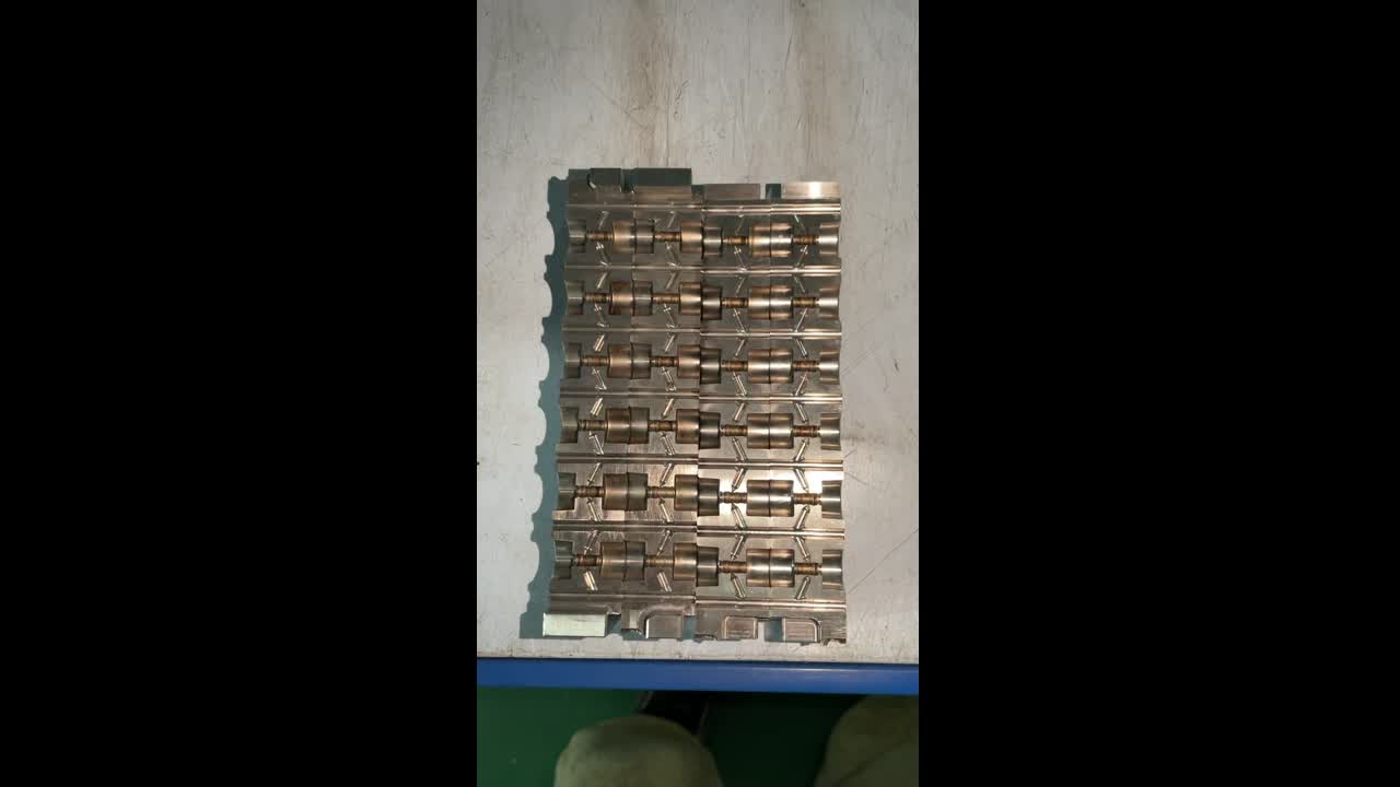
This distribution explains why conformal cooling has such a large impact on total cycle time. Conventional straight-drilled cooling lines cannot follow the part geometry, which creates hot spots where heat extraction is slow. These hot spots become the bottleneck — the cooling timer must be set long enough for the slowest-cooling region to reach ejection temperature. Conformal cooling channels follow the part contour at a uniform distance, eliminating hot spots and allowing the entire part surface to reach ejection temperature simultaneously.
The result is that cooling time can be reduced by 30–60%, and since cooling represents the majority of total cycle time, overall cycle time reductions of 20–50% are consistently achievable. For a deeper look at the mechanisms, see our guide on conformal cooling channels.
2. How We Measured Cycle Time Reduction
All 53 projects in this data set were measured using a consistent methodology to ensure comparable results:
The existing mold with conventional (straight-drilled) cooling was run for a minimum of 200 consecutive shots at steady-state conditions. We recorded: total cycle time (clamp close to clamp close), cooling time setpoint, mold surface temperature at 4–8 thermocouple locations, part temperature at ejection, and scrap rate. All measurements were taken after at least 30 minutes of continuous production to ensure thermal equilibrium.
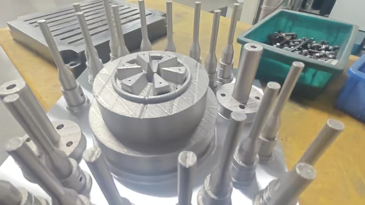
Conformal cooling inserts were installed in the same mold base. No other changes were made to the mold — same resin lot, same machine, same coolant temperature, same flow rate. This isolation ensures that any cycle time change is attributable solely to the cooling channel geometry.
With conformal inserts installed, the process engineer progressively reduced cooling time while monitoring part quality (dimensional checks, warpage, sink marks, ejection force). The cooling time was reduced until parts just met quality specifications. A minimum of 200 consecutive shots were then recorded at the new optimized cycle.
Cycle time reduction is calculated as:
Note that we measure total cycle time, not just cooling time. This is the metric that matters for production throughput and machine utilization. Since injection, pack/hold, and mold movement times remain constant, the total cycle time reduction percentage is always lower than the cooling time reduction percentage.
3. Reduction Percentages by Part Type
The table below summarizes cycle time reduction results across all 53 projects, grouped by part type. Each row represents the range and median observed across multiple projects in that category.
| Part Type | Projects (n) | Cycle Time Reduction Range | Median Reduction | Typical Cycle Time Before | Typical Cycle Time After |
|---|---|---|---|---|---|
| Thin-Wall Containers | 11 | 20–35% | 26.8% | 8.5–14s | 5.8–10.2s |
| Automotive Panels | 14 | 25–40% | 31.2% | 28–48s | 18–33s |
| Medical Device Components | 9 | 30–50% | 38.6% | 18–35s | 10–22s |
| Packaging Caps & Closures | 12 | 15–25% | 19.4% | 5.2–9s | 4.0–7.2s |
| Electronic Housings | 7 | 20–35% | 27.1% | 22–38s | 15–28s |
Detailed Breakdown: Thin-Wall Containers (20–35% Reduction)
Thin-wall containers (wall thickness 0.4–1.2 mm) such as food packaging, disposable cups, and cosmetic jars present a unique cooling challenge. The thin walls cool quickly, but localized hot spots at gate areas and corners still create bottlenecks. Conformal cooling delivers a median 26.8% reduction by eliminating these hot spots, though the absolute time savings per shot is smaller (typically 2–4 seconds) due to the already-short baseline cycles. At high-cavitation counts (16–64 cavities), even a 2-second reduction translates into massive annual throughput gains.
Detailed Breakdown: Automotive Panels (25–40% Reduction)
Automotive interior trim, door panels, and structural brackets in automotive injection molding showed the most consistent results, with 12 of 14 projects falling between 27% and 37% reduction. These parts combine thick-to-thin wall transitions, deep ribs, and large surface areas that make conventional cooling highly inefficient. The median 31.2% reduction reflects 8–15 seconds of absolute time savings per shot.
Detailed Breakdown: Medical Device Components (30–50% Reduction)
Medical device components showed the widest range and highest median reduction. This is because medical parts are often molded from semi-crystalline engineering resins (POM, PEEK, PA) at elevated mold temperatures where thermal management is critical. Complex geometries with deep cores, thin walls, and tight tolerance requirements mean that conventional cooling creates significant temperature gradients. Conformal cooling eliminates these gradients, enabling aggressive cooling time reductions while simultaneously improving dimensional consistency.
Detailed Breakdown: Packaging Caps (15–25% Reduction)
Packaging caps and closures showed the lowest reduction percentages but remain highly profitable projects due to extremely high production volumes (often 5–50 million shots per year per tool). The relatively modest reduction reflects the fact that cap molds already use efficient cooling designs, and the baseline cycle times are short (5–9 seconds). At these volumes, even a 15% reduction generates substantial annual savings.
Detailed Breakdown: Electronic Housings (20–35% Reduction)
Electronic housings, connector enclosures, and switch covers molded in ABS, PC, and PC/ABS blends showed consistent reductions of 20–35%. These parts typically have uniform wall thickness but include multiple bosses, snap fits, and internal ribs that create isolated hot spots with conventional cooling. Conformal channels target these specific areas.
Cycle Time Reduction by Resin Type
Resin type has a measurable effect on reduction percentage. Semi-crystalline resins benefit more from uniform cooling because crystallization behavior is temperature-dependent.
| Resin Category | Common Resins | Avg. Cycle Time Reduction | Mold Temp Range |
|---|---|---|---|
| Semi-Crystalline (Standard) | PP, PE, POM | 25–35% | 20–80°C |
| Semi-Crystalline (Engineering) | PA6, PA66, PBT, PPS | 30–45% | 60–140°C |
| Amorphous (Standard) | ABS, PS, SAN | 20–28% | 40–80°C |
| Amorphous (Engineering) | PC, PC/ABS, PMMA | 22–32% | 70–120°C |
| High-Performance | PEEK, PEI, LCP | 35–50% | 150–200°C |
4. Three Case Studies with Before/After Numbers
Part: Interior air vent bezel, PP+T20, wall thickness 2.0–3.5 mm, part weight 48g
Production volume: 800,000 shots/year on a 350-ton press at $92/hr
| Parameter | Conventional Cooling | Conformal Cooling | Change |
|---|---|---|---|
| Total Cycle Time | 38.2s | 25.6s | −33.0% |
| Cooling Time | 24.0s | 12.8s | −46.7% |
| Max Mold Surface ΔT | 18.4°C | 4.2°C | −77% |
| Warpage (max) | 0.42 mm | 0.14 mm | −67% |
| Scrap Rate | 6.2% | 0.8% | −87% |
Part: Insulin pen outer housing, POM (Delrin 500P), wall thickness 1.2–1.8 mm, part weight 12.4g
Production volume: 3,200,000 shots/year on a 180-ton press at $78/hr
| Parameter | Conventional Cooling | Conformal Cooling | Change |
|---|---|---|---|
| Total Cycle Time | 22.8s | 13.2s | −42.1% |
| Cooling Time | 15.6s | 7.0s | −55.1% |
| Max Mold Surface ΔT | 14.6°C | 2.8°C | −81% |
| Dimensional Cpk | 1.12 | 2.04 | +82% |
| Scrap Rate | 3.8% | 0.4% | −89% |
Part: 28mm flip-top cap, HDPE, wall thickness 1.0–1.4 mm, part weight 3.2g
Production volume: 18,000,000 shots/year on a 250-ton press at $82/hr
| Parameter | Conventional Cooling | Conformal Cooling | Change |
|---|---|---|---|
| Total Cycle Time | 7.8s | 6.2s | −20.5% |
| Cooling Time | 4.6s | 3.2s | −30.4% |
| Cavity-to-Cavity ΔT | 8.2°C | 1.6°C | −80% |
| Scrap Rate | 2.1% | 0.3% | −86% |
For more real-world production data, see our case studies page and our detailed conformal cooling ROI analysis.
5. Factors That Affect Reduction Magnitude
Not every project achieves the same cycle time reduction. Based on our data set, five primary factors explain most of the variation:
Parts with thick walls (>3 mm) or large wall thickness variation (thick-to-thin ratios above 2:1) see larger reductions because conventional cooling is least effective on thick sections. Our data shows a clear correlation: parts with nominal wall thickness above 3.0 mm averaged 34.2% cycle time reduction, versus 23.8% for parts below 1.5 mm.
Semi-crystalline resins (PA, POM, PBT, PEEK) benefit more than amorphous resins (ABS, PC, PMMA) because crystallization is highly temperature-sensitive. Non-uniform cooling causes uneven crystallinity, which leads to warpage and dimensional variation. Conformal cooling enables faster cooling while maintaining crystallinity uniformity, producing both shorter cycles and better parts. High-temperature resins processed above 100°C mold temperature show the largest reductions.
Parts with deep cores, tall ribs, complex undercuts, and multiple bosses create areas where straight-drilled cooling lines simply cannot reach. These "cooling deserts" become the bottleneck. The more complex the part geometry, the larger the gap between conventional and conformal cooling performance. Simple flat parts with uniform walls show the smallest improvement (15–20%), while complex 3D geometries show the largest (35–50%).
Molds with well-designed conventional cooling (multiple independent circuits, baffles in cores, proper flow rates) show smaller improvement when upgraded to conformal cooling because the baseline is already reasonably good. Molds with poor existing cooling — a single series circuit, no baffles, large distances from cooling line to cavity surface — show dramatic improvement. In our data, the worst-cooled conventional molds showed 40–50% cycle time reduction with conformal inserts.
Multi-cavity molds benefit from improved cavity-to-cavity temperature uniformity. With conventional cooling, outer cavities often run hotter than inner cavities, forcing the cycle time to accommodate the slowest-cooling cavity. Conformal cooling equalizes temperatures across all cavities, allowing the cycle to be set based on the average rather than the worst case. We observed 3–5% additional cycle time improvement attributable to cavity equalization in molds with 8 or more cavities.
Understanding these factors helps predict the expected reduction for your specific application. For a guide on designing channels to maximize these benefits, see our conformal cooling design article and channel design guidelines.
6. How to Calculate Annual Savings from Cycle Time Reduction
The financial impact of cycle time reduction depends on three variables: how many shots you run per year, your machine hourly rate, and the magnitude of cycle time reduction. Here is the formula we use for all conformal cooling benefits analyses:
Annual shots: 600,000
Original cycle time: 32.0 seconds
New cycle time (conformal): 21.4 seconds (33.1% reduction)
Machine rate: $88/hour
Calculation: 600,000 × (32.0 − 21.4) / 3600 × $88 = $155,467/year
Conformal insert cost: $3,600
Quick Reference: Annual Savings by Volume and Reduction
The following table shows estimated annual throughput savings for different production volumes and cycle time reduction levels. Assumes a $85/hr machine rate and 30-second baseline cycle time.
| Annual Shots | 15% Reduction (25.5s) | 25% Reduction (22.5s) | 35% Reduction (19.5s) | 45% Reduction (16.5s) |
|---|---|---|---|---|
| 100,000 | $15,938 | $26,563 | $37,188 | $47,813 |
| 250,000 | $39,844 | $66,406 | $92,969 | $119,531 |
| 500,000 | $79,688 | $132,813 | $185,938 | $239,063 |
| 1,000,000 | $159,375 | $265,625 | $371,875 | $478,125 |
| 5,000,000 | $796,875 | $1,328,125 | $1,859,375 | $2,390,625 |
These figures represent machine time savings only. Total savings including reduced scrap, lower energy costs, and reduced labor per part are typically 30–50% higher. For a complete financial model including NPV calculations, see our conformal cooling ROI guide and cost analysis.
7. Statistical Analysis of Results
To provide full transparency on the data, here are the statistical parameters for the complete 53-project data set:
| Statistical Measure | Value |
|---|---|
| Sample size (n) | 53 projects |
| Mean cycle time reduction | 28.4% |
| Median cycle time reduction | 27.6% |
| Standard deviation | 8.3 percentage points |
| Minimum reduction observed | 12.8% (thin-wall PP cap, already well-cooled mold) |
| Maximum reduction observed | 51.2% (PEEK medical component, deep core) |
| 95% confidence interval for mean | 26.1% – 30.7% |
| Interquartile range (IQR) | 22.0% – 34.5% |
Distribution of Results
The distribution of cycle time reductions across all 53 projects follows an approximately normal pattern with a slight right skew (toward higher reductions). Here is the frequency breakdown:
| Reduction Range | Number of Projects | Percentage of Total | Primary Applications |
|---|---|---|---|
| 10–19% | 7 | 13.2% | Caps/closures, thin-wall with good existing cooling |
| 20–29% | 19 | 35.8% | Containers, electronic housings, standard automotive |
| 30–39% | 18 | 34.0% | Complex automotive, medical, engineering resins |
| 40–50%+ | 9 | 17.0% | High-temp resins, deep-core medical, complex multi-cavity |
Key finding: 86.8% of all projects achieved cycle time reductions of 20% or greater. Only 2 of 53 projects (3.8%) achieved less than 15% reduction, and both involved molds that already had well-optimized conventional cooling designs.
Correlation Analysis
We tested the correlation between cycle time reduction and several independent variables across the data set:
- Wall thickness vs. reduction: Pearson r = 0.64 (moderate positive correlation). Thicker parts benefit more from conformal cooling.
- Mold temperature vs. reduction: Pearson r = 0.71 (strong positive correlation). Higher mold temperatures amplify the advantage of conformal channels.
- Part complexity (subjective 1–5 scale) vs. reduction: Spearman ρ = 0.58 (moderate positive correlation). More complex geometries benefit more.
- Number of cavities vs. reduction: Pearson r = 0.23 (weak positive correlation). Cavity count has a small but measurable effect through improved equalization.
These correlations support the five-factor model described in Section 5 and can help engineers predict the likely reduction range for new projects. For simulation-based prediction before committing to conformal inserts, see our conformal cooling simulation workflow guide.
8. Frequently Asked Questions
Across 53 production projects, the average (mean) cycle time reduction is 28.4%, with a median of 27.6%. Results range from 12.8% on well-optimized thin-wall molds to 51.2% on complex medical device molds running high-temperature resins. Most projects (87%) achieve reductions of 20% or greater.
Cycle time reduction must be measured under controlled conditions: same machine, same resin lot, same coolant temperature, and minimum 200 consecutive shots at steady state. The key metric is total clamp-to-clamp cycle time (not just cooling time), as this determines actual production throughput. Comparing cooling time alone overstates the improvement because injection, pack/hold, and mold movement times remain constant.
Medical device components and complex automotive parts show the largest reductions (30–50% and 25–40% respectively). Parts with thick walls, deep cores, high-temperature resins, and complex geometries benefit the most because these features create the largest thermal management challenges for conventional cooling.
No. While cycle time reduction drives the primary ROI, conformal cooling also reduces warpage and dimensional variation (often by 50–80%), lowers scrap rates (typically from 3–8% to below 1%), improves surface quality, and extends mold life by reducing thermal stress cycling. See our complete conformal cooling benefits guide for all five benefit categories.
Start with the data tables in this article to establish a likely range based on your part type and resin. For a more precise prediction, run a Moldflow simulation comparing conventional and conformal channel designs. MouldNova offers free simulation analysis for qualifying projects — contact us to discuss your application.
Send us your part CAD and current cycle data. We will run a thermal simulation and provide a predicted cycle time reduction percentage and ROI calculation — free of charge for qualifying projects.
Request Free Analysis →Related Pages
- Conformal Cooling Benefits — Five Benefit Categories with a 3-Year Factory Model
- Conformal Cooling ROI: Payback Period, Annual Savings & 5-Year NPV Calculator
- Conformal Cooling Injection Molding — Complete Technical Guide
- Conformal Cooling for Automotive Injection Molding
- Conformal Cooling for Medical Device Injection Molding
- Conformal Cooling vs Conventional Cooling — Side-by-Side with 13 Real Projects
- Conformal Cooling Inserts — Service Details & Specifications
- Case Studies — Full Production Data from Real Programs