1. Introduction: Why Mold Shops Are Looking Beyond Conformal Cooling
Conformal cooling has been the gateway application for metal 3D printing in injection molding — and for good reason. The cycle time reductions of 25–40% and scrap improvements are well documented. But conformal cooling channels represent only one category of value that metal 3D printing can deliver to injection mold operations.
As LPBF (Laser Powder Bed Fusion) technology has matured — with larger build volumes, faster scan speeds, and a wider range of qualified tool steel powders — mold shops and OEMs are discovering that the same machines producing conformal cooling inserts can solve a range of other tooling challenges. Venting problems, mold weight, complex parting geometries, prototype tooling timelines, and legacy spare part shortages are all problems where additive manufacturing provides solutions that conventional machining cannot match.
This guide covers six distinct metal AM applications for injection molds beyond conformal cooling, the LPBF process fundamentals that make them possible, material selection for different mold requirements, the hybrid manufacturing workflow that delivers production-grade results, and the cost justification framework that determines which applications make financial sense.
At MouldNova, our metal 3D printing service processes over 200 mold inserts per year. While conformal cooling remains the most common application, approximately 35% of our projects now involve one or more of the additional AM applications discussed in this article.
2. LPBF Process Overview for Mold Components
Laser Powder Bed Fusion (LPBF), also known as Selective Laser Melting (SLM) or Direct Metal Laser Sintering (DMLS), is the dominant metal AM process for mold components. Understanding its capabilities and constraints is essential for identifying which mold applications are viable candidates for additive manufacturing.
How LPBF Works for Mold Inserts
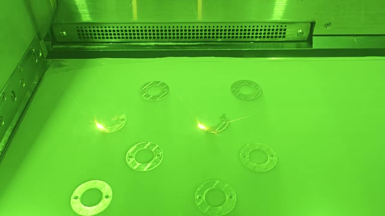
The process builds parts layer by layer from metal powder using a high-power fiber laser (typically 200–700W). Each layer is 20–50 micrometers thick. The laser selectively melts powder particles, fusing them to the layer below. After each layer, a recoater blade spreads a fresh powder layer, and the process repeats.
Layer thickness: 20–40 μm (thinner layers = better surface finish, longer build time)
Laser power: 200–400W for tool steels, 300–700W for copper alloys
Scan speed: 600–1200 mm/s depending on material and required density
Build volume: Typical machines offer 250 × 250 × 300 mm, with large-format machines reaching 400 × 400 × 400 mm
Achievable density: >99.5% (fully dense for mold applications)
As-printed surface roughness: Ra 6–12 μm (requires post-machining for mold surfaces)
For mold applications, the process delivers parts with mechanical properties equivalent to or exceeding wrought material after appropriate heat treatment. Maraging steel (MS1) achieves 50–54 HRC after age hardening — suitable for production molds running millions of shots.
Build Orientation for Mold Inserts
Build orientation significantly affects part quality and cost. For mold inserts, the parting surface is typically oriented upward (parallel to the build platform) to minimize support structures on critical surfaces and ensure the best dimensional accuracy on mating faces. Internal channels and lattice structures are oriented to be self-supporting wherever possible, using teardrop or diamond cross-sections rather than circular profiles to avoid support structures inside channels that cannot be removed.
3. Six AM Applications Beyond Conformal Cooling
3.1 Micro-Porous Venting Inserts
Gas traps are one of the most persistent quality problems in injection molding. Conventional venting relies on machined vent slots (typically 0.02–0.05 mm deep) at the parting line, but many gas trap locations occur far from the parting line — in deep ribs, boss features, and the last-to-fill areas of complex geometries.
Metal 3D printing enables a fundamentally different approach: micro-porous venting inserts. By deliberately controlling LPBF process parameters (laser power, scan spacing, and hatch strategy), it is possible to create regions with controlled porosity — interconnected micro-pores of 20–80 micrometers that allow gas to escape while preventing plastic melt from penetrating the surface.
A consumer electronics housing with 35mm-deep ribs suffered persistent burn marks at the rib tips — a classic gas trap location inaccessible by conventional venting. A 3D-printed micro-porous venting insert placed at the rib tip eliminated burn marks completely, reducing cosmetic rejects from 12% to under 0.5% without adding any visible witness lines on the part surface.
3.2 Topology-Optimized Mold Components
Large mold bases and support plates are traditionally solid steel blocks, contributing to mold weights of 2,000–10,000 kg for automotive and appliance tools. Topology optimization algorithms, combined with LPBF's ability to produce complex internal geometries, can reduce component weight by 30–50% while maintaining or even increasing stiffness.
Weight reduction in mold components delivers several operational benefits: faster mold changes on the press, reduced crane and handling requirements, lower shipping costs, and extended press platen life. For 3D printed mold inserts that operators handle manually, weight reduction directly improves ergonomics and safety.
| Component | Conventional Weight | Topology-Optimized | Reduction |
|---|---|---|---|
| Core insert (medium) | 18.5 kg | 11.2 kg | 39% |
| Ejector plate section | 32.0 kg | 19.8 kg | 38% |
| Slide carrier | 8.4 kg | 4.6 kg | 45% |
| Hot runner manifold block | 24.0 kg | 14.9 kg | 38% |
3.3 Complex Parting Line Inserts
Parting line inserts with complex 3D contours, sharp transitions, and tight radii are among the most expensive and time-consuming mold components to machine conventionally. Multi-axis CNC programming, multiple setups, and extensive EDM operations drive lead times of 3–6 weeks for complex parting line geometries.
LPBF builds these geometries in a single operation regardless of complexity. Undercuts, compound curves, and features that would require wire EDM or sinker EDM can be printed directly. The as-printed insert requires only finish machining on mating surfaces and polishing on molding surfaces — eliminating the most time-intensive conventional manufacturing steps.
3.4 Multi-Material Inserts
Different regions of a mold insert often have conflicting material requirements. The core pin area may need high thermal conductivity to extract heat from a thick boss, while the surrounding cavity surface needs high hardness to resist wear from glass-filled resins. Conventionally, this requires separate inserts made from different materials, with thermal interface losses at the joints.
Advanced LPBF systems can transition between materials within a single build — or more practically, copper alloy thermal pins can be printed and pressed into 3D-printed steel inserts with optimized interface geometries that maximize thermal contact. This approach delivers thermal conductivity of 200–380 W/m·K in targeted zones while maintaining 50+ HRC hardness on wear surfaces.
3.5 Rapid Tooling for Prototype Molds
Conventional prototype molds require 6–10 weeks and $15,000–50,000 depending on complexity. For product development teams running on tight timelines, this delay can push launch schedules by months. Metal 3D printing enables rapid tooling with dramatically compressed timelines.
A 3D-printed prototype mold insert in maraging steel can produce 1,000–10,000 shots — sufficient for material validation, dimensional verification, and functional testing with production-intent resin. The insert fits into a standard MUD frame or universal mold base, eliminating the need for a dedicated prototype mold base. Total cost is typically $2,000–8,000 depending on size and complexity, delivered in 5–10 business days.
3.6 Spare Part Production for Legacy Molds
Molds built 15–30 years ago often lack complete CAD data, and the original toolmakers may no longer be in business. When a core pin breaks, a slide wears out, or a cavity insert cracks, producing a replacement through conventional methods requires reverse engineering, new CNC programming, and potentially new EDM electrodes — a process that can take 4–8 weeks.
Metal 3D printing offers a faster alternative: 3D scan the worn or broken component (or the molded part for negative geometry), generate a CAD model, and print a replacement insert. This approach is particularly valuable for complex components where the original manufacturing method involved extensive EDM or multi-axis machining. Lead time drops to 5–10 days, and the replacement can incorporate design improvements such as conformal cooling channels or improved venting that were not in the original design.
4. Design Freedom Enabled by Additive Manufacturing
The fundamental advantage of LPBF for mold components is design freedom — the ability to create internal and external geometries that are impossible or prohibitively expensive with subtractive manufacturing. This design freedom manifests in several specific capabilities relevant to injection molds.
Lattice Structures
LPBF can produce internal lattice structures with strut diameters as small as 0.3 mm and cell sizes of 2–8 mm. In mold applications, lattice structures serve multiple functions: weight reduction (replacing solid material with 70–85% void space while maintaining structural integrity), enhanced heat transfer (increasing surface area for coolant contact), and controlled compliance (enabling localized flexibility in ejector mechanisms or shut-off surfaces).
Internal Features
Conventional machining cannot create features inside a solid block — all features must be accessible from an external surface. LPBF removes this constraint entirely. Internal cooling channels, pressure sensor cavities, thermocouple wells, and gas evacuation paths can be placed anywhere within the insert volume, following optimized paths that are impossible to drill or machine.
Complex Surfaces
Freeform surfaces, sharp internal corners, deep narrow slots, and compound curves that require multiple EDM setups in conventional toolmaking are produced in a single LPBF build with no additional setup cost regardless of geometric complexity. This capability is particularly valuable for medical device molds with complex anatomical surfaces, optical molds with freeform lens geometries, and consumer product molds with organic design language.
While geometric complexity does not add cost in LPBF (unlike CNC where complexity directly drives programming and machining time), AM has its own design rules: minimum wall thickness of 0.3–0.5 mm, overhang angles above 45 degrees for unsupported features, and minimum hole diameters of 0.5 mm for self-supporting horizontal channels. Effective mold design for AM requires understanding both the freedoms and the constraints.
5. Material Options for 3D-Printed Mold Components
Material selection for AM mold components depends on the specific application requirements: hardness for wear resistance, thermal conductivity for heat management, corrosion resistance for aggressive resins, and machinability for post-processing. The table below summarizes the primary material options available for LPBF mold components.
| Material | Hardness | Thermal Cond. | Best For |
|---|---|---|---|
| Maraging Steel MS1 (18Ni300) | 50–54 HRC (aged) | ~20 W/m·K | General mold inserts, conformal cooling, rapid tooling |
| H13 Tool Steel | 48–52 HRC (Q&T) | ~25 W/m·K | High-temperature molds, die casting, long-run production tools |
| Corrax / Stainless | 48–50 HRC (aged) | ~15 W/m·K | Corrosion-resistant molds (PVC, POM, flame-retardant resins) |
| 316L Stainless | 25–30 HRC | ~15 W/m·K | Medical/food-contact molds, low-wear applications |
| CuCrZr Copper Alloy | ~25 HRC | ~320 W/m·K | Thermal management inserts, hot spots in thick-wall areas |
| GRCop-42 (Cu-Cr-Nb) | ~20 HRC | ~280 W/m·K | High-conductivity inserts with better strength retention at temperature |
Maraging steel MS1 is the workhorse material for mold applications. It offers an excellent combination of printability (low cracking tendency, minimal residual stress), post-processing flexibility (can be age-hardened without quenching, minimizing distortion), and performance (50+ HRC hardness, good polishability to SPI A-2/A-3). Approximately 70–80% of all LPBF mold inserts are produced in MS1.
H13 tool steel is gaining adoption for applications requiring hot hardness retention above 200°C or direct compatibility with existing mold specifications that call out H13. However, H13 is more challenging to print than MS1 — it requires preheated build platforms (200–400°C) and careful parameter optimization to avoid cracking from high carbon content.
Copper alloys are used as thermal management inserts rather than complete mold inserts due to their lower hardness. A common approach is to print a CuCrZr insert for a localized hot spot area and press-fit it into a surrounding maraging steel insert, combining the thermal conductivity of copper (320 W/m·K) with the wear resistance of hardened steel (50+ HRC).
6. Hybrid Manufacturing: 3D Print + CNC Finish
Production mold inserts are virtually never used in their as-printed state. The standard workflow is hybrid manufacturing: LPBF builds the near-net-shape insert including all internal features (cooling channels, venting structures, lattice regions), then CNC machining finishes all external mating and molding surfaces to final dimensions and surface quality.
Add 0.5–1.0 mm stock allowance on all surfaces that require CNC finishing. Design internal features (channels, vents, lattice) to final dimensions since they cannot be post-machined. Include datum features for fixturing the printed part on the CNC machine.
Print the insert with optimized orientation and support strategy. After build completion, stress relieve in a vacuum furnace (typically 600°C for 2 hours for MS1) before removing from the build plate. This minimizes distortion during subsequent machining.
Age harden MS1 at 490°C for 6 hours to achieve 50–54 HRC. Unlike conventional quench-and-temper heat treatment for H13 or P20, MS1 age hardening produces minimal distortion (<0.05 mm on typical insert sizes), which is a major practical advantage for maintaining dimensional accuracy on finished features.
Machine all mating surfaces, parting surfaces, and cavity/core surfaces to final dimensions. Typical tolerances achieved: ±0.01–0.02 mm on critical dimensions. Polish molding surfaces to required SPI finish (A-2, A-3, B-1, etc.). EDM texturing can be applied to 3D-printed inserts using the same methods as conventional inserts.
CMM inspection of all critical dimensions. CT scanning for internal channel verification (confirming channels are clear and dimensionally accurate). Leak testing of cooling circuits at 6–10 bar. Flow testing to verify cooling circuit pressure drop matches simulation predictions.
The hybrid approach delivers the best of both worlds: AM's design freedom for internal features and complex geometries, combined with CNC's precision and surface quality for functional interfaces. Total lead time for a hybrid mold insert is typically 10–15 business days — significantly faster than the 4–8 weeks required for complex conventionally machined inserts with EDM operations.
7. When to Print the Entire Insert vs. Just Adding Channels
One of the most common questions from mold engineers evaluating AM is whether to print the complete insert or just retrofit conformal cooling channels into an existing conventional design. The answer depends on several factors.
| Factor | Print Entire Insert | Channels Only (Retrofit) |
|---|---|---|
| Insert size | <200mm in any dimension | Any size (channels are small) |
| Internal features needed | Venting, lattice, sensors | Cooling only |
| External geometry | Complex (saves CNC/EDM) | Simple (CNC is efficient) |
| Lead time priority | Fastest (single workflow) | Requires insert + channel assembly |
| Cost sensitivity | Higher AM cost per insert | Lower total cost for large inserts |
| Production volume | Any (MS1 = 1M+ shots) | Any |
| Rapid tooling / prototyping | Ideal | Not applicable |
Print the entire insert when: the insert is small enough to fit economically in the build volume, the geometry is complex enough that CNC/EDM would be expensive, you need internal features beyond just cooling, or you need the insert fast for rapid tooling. The crossover point where printing the entire insert becomes more expensive than conventional machining + AM channels is typically around 150–200 mm insert dimension, though this varies with geometric complexity.
Use channel-only retrofit when: the existing insert design is proven and only cooling performance needs improvement, the insert is too large for economical full printing, or when the external geometry is simple enough that CNC machining is straightforward and cost-effective.
8. Cost Justification for Different AM Mold Applications
Each AM application has a different cost justification profile. The table below provides typical cost ranges and payback mechanisms for each application category.
| Application | Typical AM Cost | Primary Savings Mechanism | Typical Payback |
|---|---|---|---|
| Conformal cooling insert | $1,500–5,000 | Cycle time reduction (25–40%) | 1–4 weeks |
| Micro-porous venting insert | $800–3,000 | Scrap reduction (burn marks, shorts) | 2–8 weeks |
| Topology-optimized component | $3,000–15,000 | Handling cost, mold change time, shipping | 6–18 months |
| Complex parting line insert | $2,000–8,000 | Lead time reduction (vs. EDM) | Immediate (time savings) |
| Rapid tooling insert | $2,000–8,000 | Weeks saved in product development | Immediate (time-to-market) |
| Legacy spare part | $1,500–6,000 | Avoided production downtime | Immediate (downtime cost) |
Problem: Gas trap causing burn marks on a medical device housing. Scrap rate: 8%. Annual production: 500,000 parts. Part value: $3.50.
Annual scrap cost: 500,000 × 8% × $3.50 = $140,000/year
AM venting insert cost: $2,200 (design + print + finish)
Expected scrap reduction: 8% → 0.5% = 7.5% improvement
Annual savings: 500,000 × 7.5% × $3.50 = $131,250/year
Payback period: 6.1 days
Conventional prototype mold: $28,000, 8-week lead time
3D-printed rapid tool insert + MUD frame: $5,500, 8-day lead time
Direct cost savings: $28,000 − $5,500 = $22,500
Time savings: 8 weeks − 8 days = ~6.5 weeks earlier to market
If product launch revenue = $200,000/month: 6.5 weeks earlier = ~$325,000 in accelerated revenue
Total value of AM rapid tooling: $347,500 vs. $5,500 cost
9. Quality Requirements for AM Mold Components
Production mold inserts must meet stringent quality requirements regardless of manufacturing method. For AM components, the following quality parameters must be verified and documented.
Density and Porosity
LPBF parts must achieve >99.5% relative density for mold applications. Porosity is measured via Archimedes method or metallographic cross-section analysis. CT scanning provides volumetric porosity mapping for critical inserts. Density below 99.0% indicates process problems that compromise mechanical properties and polishability.
Dimensional Accuracy
As-printed dimensional accuracy is typically ±0.05–0.1 mm. After CNC finishing, critical dimensions are held to ±0.01–0.02 mm. CMM inspection with full GD&T reporting is standard for production inserts. For inserts with internal channels, CT scanning verifies channel dimensions, position, and clearance.
Surface Integrity
Molding surfaces must be free of surface-connected porosity that could cause witness marks on molded parts. After polishing, surfaces are inspected under magnification for pinholes. If surface porosity is detected, additional polishing or micro-welding can remediate isolated defects. Consistent surface quality at SPI A-2 or A-3 levels confirms that the LPBF process parameters are properly optimized.
Mechanical Properties
Tensile testing of witness coupons (printed alongside the insert in the same build) verifies that material properties meet specifications. For MS1 after age hardening: UTS ≥ 1,900 MPa, yield strength ≥ 1,800 MPa, hardness 50–54 HRC, elongation ≥ 2%. These properties ensure the insert can withstand injection pressures of 80–200 MPa over millions of cycles.
| Quality Parameter | Requirement | Test Method |
|---|---|---|
| Density | >99.5% | Archimedes / metallography / CT scan |
| Hardness (MS1 aged) | 50–54 HRC | Rockwell C hardness test |
| Surface finish (polished) | Ra ≤ 0.2 μm (SPI A-3) | Profilometer |
| Dimensional tolerance | ±0.01–0.02 mm (finished) | CMM inspection |
| Internal channel integrity | No blockages, correct geometry | CT scan + flow test |
| Cooling circuit leak test | No leaks at 10 bar, 30 min hold | Pressure decay test |
| Material traceability | Powder lot, build ID, heat treatment record | Documentation package |
10. Frequently Asked Questions
Beyond conformal cooling channels, metal 3D printing enables micro-porous venting inserts that eliminate gas traps without witness lines, topology-optimized mold components that reduce weight by 30–50%, complex parting line inserts with geometries impossible to machine conventionally, multi-material inserts combining thermal conductivity zones, rapid tooling for prototype molds delivered in 5–10 days, and on-demand spare part production for legacy molds where original tooling data may be incomplete.
Print the entire insert when the geometry requires internal features beyond cooling channels (venting, lattice structures), the insert is small enough to fit within the build volume economically (typically under 200 mm in any dimension), or when you need the insert urgently for rapid tooling. Use conventional machining with only 3D-printed conformal cooling channel inserts when the insert is large, the external geometry is simple enough to machine, or when only the cooling performance needs improvement. The hybrid approach — 3D print + CNC finish — often provides the best balance of AM design freedom and machined surface quality.
The most common materials for LPBF mold components are Maraging Steel (MS1/18Ni300) at 50–54 HRC after age hardening for most mold applications, H13 Tool Steel for high-temperature applications above 200°C, Stainless Steel 316L for corrosion-resistant molds processing PVC or other corrosive resins, and CuCrZr or GRCop-42 copper alloys for thermal management inserts requiring conductivity 3–5x higher than steel. Material selection depends on the specific mold application, required hardness, thermal conductivity needs, and corrosion resistance requirements.
As-printed LPBF surfaces typically measure Ra 6–12 micrometers, which is too rough for most molding surfaces. After CNC finishing, surfaces reach Ra 0.4–0.8 micrometers. With polishing, Ra 0.05–0.2 micrometers is achievable — meeting SPI A-2 to A-3 standards required for optical and cosmetic parts. The hybrid manufacturing approach (3D print near-net shape, then CNC finish critical surfaces) is standard practice for production mold inserts.
A 3D-printed mold insert typically costs 1.5–3x more than a conventionally machined equivalent when comparing manufacturing cost alone. However, the total cost of ownership shifts in favor of AM when you factor in cycle time savings from conformal cooling (often $50,000–200,000/year on high-volume tools), reduced scrap rates, elimination of EDM operations for complex internal features, and compressed lead times. For rapid tooling applications, 3D-printed prototype mold inserts at $2,000–8,000 delivered in 5–10 days are significantly cheaper than conventional prototype molds at $15,000–50,000 taking 6–10 weeks.
Whether you need conformal cooling, venting inserts, rapid tooling, or complex geometry — our engineering team can evaluate your mold design and recommend the right AM approach. Send your insert CAD for a free feasibility review.
Request a Free AM Feasibility Review →Related Pages
- Metal 3D Printing Service — Process Capabilities & Materials
- 3D Printed Mold Inserts — Full-Chain Service from Design to Delivery
- Rapid Tooling Service — Prototype Molds in Days, Not Months
- Conformal Cooling Benefits — Five Benefit Categories with a 3-Year Factory Model
- Conformal Cooling ROI: Payback Period, Annual Savings & 5-Year NPV Calculator
- Conformal Cooling Design Guide — Channel Sizing, Layout Rules & Simulation Tips
- Case Studies — Full Production Data from Real Programs