- How to design the mold base to properly accommodate conformal inserts
- Parting line placement and its effect on insert sealing
- Water connection positioning, routing, and fitting selection
- Sealing methods: O-ring grooves, face sealing, and sealant best practices
- Material selection — mold base vs. insert: why they differ and why that matters
- Integration with hot runner systems: thermal isolation requirements
- Tolerance stack and pocket machining specifications
- Ejector pin coordination: design sequencing to avoid conflicts
Table of Contents
- Design Philosophy: Mold Base + Conformal Insert as a System
- Mold Base Design for Conformal Insert Accommodation
- Parting Line Placement
- Water Connection Positioning and Routing
- Sealing Methods
- Material Selection: Mold Base vs. Conformal Insert
- Hot Runner Integration
- Tolerance Considerations
- Ejector Pin Coordination
- FAQ
Design Philosophy: Mold Base + Conformal Insert as a System
Conformal cooling mold design is not simply "design a mold, then add conformal channels." The conformal cooling insert and the mold base must be co-designed from the earliest stage of the mold concept. Decisions made in the mold base — pocket depth, water port positions, ejector locations, parting geometry — directly constrain what the conformal channel designer can and cannot achieve.
The most common mistake in conformal cooling mold design is treating the insert as an afterthought. Engineers finalize the mold base, lock in ejector positions, define the parting line, and then ask: "Can conformal cooling fit in here?" The answer is often "partly" — and the result is a compromised channel layout that underperforms.
The correct design sequence is:
Part analysis and hotspot identification
Run a baseline Moldflow cooling simulation on the part geometry before committing to any mold design. Identify which zones have the longest cooling time and highest surface temperature. These define where conformal inserts are required.
Define insert envelope and channel space
For each conformal zone, determine the required insert envelope — the block of metal that will be SLM-printed. This defines the pocket geometry in the mold base. Channel routing space (minimum 8mm wall to cavity surface) must be reserved before ejector pins are placed.
Place ejectors around the insert envelope
With the insert envelope confirmed, ejector pins are positioned in the remaining space. Never place ejectors through the conformal insert — they must travel through the mold base only, entering the molded part through holes in the insert face if required (these must be designed in at step 2).
Design water routing in the mold base
With insert and ejector positions fixed, route the coolant connections from the insert water ports to the mold face fittings. Conventional drilled channels in the mold base connect the conformal insert to the manifold/chiller circuit.
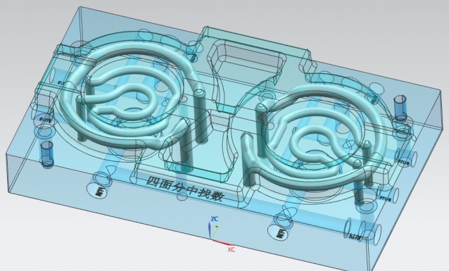
Design the conformal channel layout
Only now, with all constraints defined, does the conformal channel design proceed. The channel designer works within a fully constrained envelope with known ejector exclusion zones, water port exit positions, and pocket geometry — using design software such as Moldflow or Moldex3D to validate the layout before manufacturing.
Mold Base Design for Conformal Insert Accommodation
The mold base pocket that receives the conformal insert is a precision-machined opening. Poor pocket design is the leading cause of conformal insert fit and sealing problems in the field. Key design requirements:
Pocket geometry
The pocket should be designed with flat mating faces on all four sides and a flat bottom. Avoid angled pockets or complex 3D pocket geometries in the mold base — these increase machining cost and tolerance stack. The complexity belongs in the insert, not the pocket.
For inserts with non-rectangular cross-sections (e.g., a core insert that follows a curved part surface), design the pocket as a rectangular envelope that circumscribes the insert, then machine the insert's outer surfaces to fit this standard pocket. This keeps mold base machining simple and the tolerance achievement straightforward.
Pocket depth and locating strategy
The insert should be located in depth by contact on the bottom face, with the top face of the insert sitting flush with the mold parting plane. A positive stop on the bottom is critical: if the insert can float upward under injection pressure, it will flash at the parting line. Depth tolerance must be maintained to ±0.02mm.
For inserts heavier than approximately 5 kg, include a lifting thread (M10 minimum) in the top face of the insert for installation and removal without risk of dropping.
Lateral location
Two precision dowel pins (minimum 8mm diameter, h6/H7 fit) locate the insert laterally and prevent rotation. Position dowels on a diagonal to give unambiguous orientation — a misinstalled insert that is 180° rotated will have its IN and OUT coolant connections swapped, which is a catastrophic error discovered only after the mold is clamped.
Parting Line Placement
The conformal insert's parting-plane face (the face that aligns with the mold parting line and contacts the opposite mold half) is the highest-risk sealing surface in the system. Injection pressure during fill — typically 800–1,600 bar at the gate — acts to push the insert upward and create a flash path at this interface.
Parting line on the insert vs. mold base
The ideal arrangement is for the parting line to fall entirely within the mold base, with the conformal insert recessed below the parting plane. The insert top face contacts only the inner face of the cavity pocket, not the parting-line surface directly exposed to the injection pressure front. This is achievable when the insert is a core insert — the cavity half contains the parting-surface geometry, and the conformal insert is buried in the core pocket.
When the conformal insert must lie at the parting line (e.g., a cavity insert with complex surface geometry), ensure the insert-to-mold-base interface at the parting plane is a machined metal-to-metal contact with surface finish Ra ≤0.8μm on both faces. No sealant at the parting line — it will squeeze out under clamp force and contaminate the cavity.
Flash gap control
With the insert proud of its pocket bottom by the correct amount (flush with mold parting plane), the flash gap at the parting line is determined by the insert-to-pocket dimensional accuracy. Specify the insert top face height to +0.00/−0.01mm relative to pocket depth — this ensures the insert is never proud of the mold parting face, which would create a step visible on the part surface.
Water Connection Positioning and Routing
Water connections are the interface between the conformal insert's internal channels and the mold's external plumbing. Poor connection design is the most common cause of leaks and flow restriction.
Insert-to-Mold Base Connections
The conformal insert's channel exits (typically 4–8 per insert: multiple in/out pairs if multi-circuit) pass through the side or bottom face of the insert as machined bores. These align with corresponding bores in the mold base via O-ring sealed interfaces. The O-ring groove is machined in the mold base face, not the insert face — this protects the groove from damage during insert installation.
Mold Base to External Manifold
From the insert connection bores, conventional drilled channels in the mold base route coolant to the mold face fittings (NPT 1/4" or BSP 1/4" standard, or G1/2 for high-flow circuits). These connecting bores in the mold base are standard CNC drilling — no additive manufacturing required. Cross-drill plugs seal unused ports.
Connection Bore Diameter
All connection bores must have a minimum ID equal to the channel diameter — never smaller. Reducing the bore diameter at the insert exit (e.g., 8mm channel entering a 6mm connection bore) creates a flow restriction that increases pressure drop and reduces flow rate to below the turbulence threshold. Match bore IDs throughout: channel → insert exit bore → mold base channel → fitting bore, all the same diameter.
IN/OUT Identification
Machine IN and OUT labels next to each water fitting on the mold face. Number multiple circuits (Circuit 1 IN / Circuit 1 OUT, etc.). Use a different fitting style for IN vs. OUT if possible (e.g., straight for IN, 90° elbow for OUT) to further distinguish them. These details prevent mis-connection in the field, which causes reversed flow direction and significantly degraded cooling performance.
Water connections should exit on the operator side or top face of the mold, not through the parting-line face. Connections through the parting-line face create hose routing problems and risk pinching hoses when the mold closes.
Sealing Methods
Conformal cooling inserts operate at 6–12 bar coolant pressure. Every interface between the insert and the mold base that carries coolant requires a positive seal. Three sealing methods are used, with distinct applications:
| Sealing Method | Application | Pressure Rating | Maintenance |
|---|---|---|---|
| O-ring face seal | Insert-to-mold base water port connections | Up to 30 bar | Replace O-rings at insert removal |
| Metal-to-metal flat face contact | Insert body into pocket (non-coolant interfaces) | Structural, not fluid sealing | None required |
| Thread sealant (Loctite 577) | NPT/BSP pipe fittings at mold face | Up to 20 bar | Replace when fitting is removed |
| Copper crush washers | High-temperature applications, oil cooling circuits | Up to 40 bar | Replace at every removal |
O-ring material selection: For water at ≤90°C, use standard NBR (nitrile) O-rings, 70 Shore A. For water above 90°C or for mold temperature control oil, use EPDM O-rings. Never use silicone O-rings in water circuits — silicone degrades rapidly in pressurized water.
Material Selection: Mold Base vs. Conformal Insert
The mold base and the conformal insert deliberately use different materials with different hardness values. Understanding why informs correct material selection:
Mold Base Material
- P20 (1.2311) — most common; pre-hardened 28–34 HRC, machines cleanly, good weldability for repairs
- H13 (1.2344) — used when mold base must be harder (e.g., glass-filled materials creating abrasion on the base pocket faces); 44–52 HRC after through-hardening
- 718 (1.2738) — P20 variant with improved polishability; good for semi-transparent or appearance-critical molds
- Mold base does not need to match insert hardness — the softer base absorbs minor fit errors without galling the harder insert surface
Conformal Insert Material (select by application)
- 420 Stainless Steel — general-purpose; 48–52 HRC after heat treatment; good corrosion resistance for water cooling; most economical
- 18Ni300 Maraging Steel (1.2709) — preferred for high-injection-pressure applications (>1,200 bar) or thin wall inserts; 50–54 HRC; superior strength prevents insert deformation under load
- CuCrZr — 3× higher thermal conductivity than steel; used for gate-area inserts, high-temperature resins, or wherever maximum heat extraction is the constraint; lower hardness (38–42 HRC), not for use in abrasive resin applications
- Insert is always harder than the mold base pocket — this ensures the pocket wears before the insert if there is any mismatch-induced fretting
One additional consideration: if the conformal insert contacts the part surface and is exposed to abrasive-filled resins (glass fibre, mineral filler), a PVD hard coating (TiN or TiAlN, 3–5 μm) applied to the cavity face of the insert adds significant wear resistance without affecting dimensional accuracy meaningfully.
Hot Runner Integration
Conformal cooling molds frequently incorporate hot runner gating — the two technologies are highly complementary, as hot runners eliminate cold-runner waste while conformal cooling maximises thermal efficiency at the cavity. However, the thermal conflict between them demands careful design attention.
Thermal isolation between hot runner and conformal insert
The hot runner manifold runs at resin-specific temperatures (200–350°C depending on material). The conformal cooling insert targets mold surface temperatures of 20–80°C. These zones must be thermally isolated to prevent mutual interference:
- Insulating plate: Install a 10–15mm glass-fibre epoxy (e.g., Starlam G10) insulating plate between the hot runner backing plate and the mold base. This plate reduces conductive heat transfer from the hot manifold to the mold base by approximately 80×.
- Air gap design: Where possible, maintain a 5–10mm air gap between the hot runner manifold body and the conformal insert. Air is an excellent insulator. Do not fill this gap with steel.
- Gate insert specification: The gate insert — the steel component through which the hot nozzle tip fires into the cavity — is the highest-temperature zone in the mold. Use a CuCrZr conformal gate insert with channels pitched at 6–8mm from the gate bore centerline. The high thermal conductivity of CuCrZr extracts heat from the gate area faster than steel can, compensating for the proximity to the hot runner.
Nozzle tip accessibility
The hot nozzle tip must be accessible for removal without removing the conformal insert. Ensure that the nozzle-tip removal path (typically axial, from the hot runner side) does not pass through the conformal insert body. Design the nozzle seating pocket in the mold base or in a separate non-conformal gate bushing that can be withdrawn independently.
Tolerance Considerations for Conformal Insert Fitting
Tolerances in a conformal cooling mold are tighter than in a conventional mold because more surfaces must mate precisely. The following tolerance stack governs insert fit:
| Surface | Required Tolerance | Achieved By | Risk if Exceeded |
|---|---|---|---|
| Pocket depth (mold base) | ±0.02mm | CNC jig boring or precision milling | Insert proud of parting plane (flash) or recessed (step mark) |
| Pocket width/length (mold base) | ±0.03mm | CNC milling with finishing pass | Insert rocking, sealing face gap |
| Insert mating face height | +0.00/−0.01mm vs. pocket depth | CNC grinding of insert base face after SLM | Same as pocket depth |
| Insert cavity face position | ±0.05mm | CNC machining of cavity face after SLM | Part wall thickness variation |
| Water port bore position (insert) | ±0.1mm | CNC drilling of port exits after SLM | O-ring misalignment, leakage |
| Dowel pin hole (insert) | H7 (±0.012mm for 8mm pin) | Precision boring or reaming | Insert misalignment, rotational float |
Note that the SLM-printed insert is not delivered at these tolerances from the printer. As-printed dimensional accuracy is typically ±0.2–0.3mm. All critical dimensions are achieved by post-SLM CNC machining, carried out after stress relief and heat treatment. This is standard practice for any reputable conformal cooling supplier. See our article on conformal cooling mold supplier evaluation for what to confirm when reviewing a quote.
Ejector Pin Coordination
Ejector pins and conformal cooling channels occupy the same physical space — the mold core zone. Managing their coexistence requires disciplined design sequencing. Key rules:
- No ejectors through the conformal insert. Ejectors must travel through the mold base only. If a part feature requires ejection directly beneath a conformal insert, the insert must be designed with a through-hole at the ejector pin location. This hole is a no-go zone for conformal channels — an exclusion zone of at least 1.5× ejector diameter around each pin position.
- Ejector positions must be frozen before channel design begins. If ejectors are moved after the conformal channel design is complete, the channel layout must be re-run to route around the new no-go zones. This is a common and preventable cause of design rework.
- Minimum wall to ejector hole: 3mm. The conformal channel must maintain at least 3mm wall between the channel bore and any ejector pin hole in the insert to prevent breakthrough during SLM printing and adequate structural integrity.
- Ejector pin proximity to cavity surface: Ejector pins should be located no closer than 10mm from the cavity surface side of the conformal insert. This preserves the channel routing space and prevents stress concentration at the ejector hole rim under injection pressure.
Need Conformal Cooling Mold Design Support?
MouldNova provides full DFM review and conformal channel design as part of every project. Send your part file and current mold concept — we'll identify design conflicts before manufacturing begins.
Frequently Asked Questions
What tolerances are required when machining a mold base pocket for a conformal cooling insert?
How should water connection fittings be positioned in a conformal cooling mold?
Can a conformal cooling insert be integrated with a hot runner system?
What is the best mold base material when combining with SLM conformal cooling inserts?
Related Articles & Pages
- Conformal Cooling Channel Design: Parameters & Engineering Workflow
- Conformal Cooling Simulation: Setup, Results Interpretation & When to Trust It
- Conformal Cooling Mold: Complete Buyer's Guide — Types, Pricing, Supplier Evaluation
- Conformal Cooling Design: Decision Framework & Application Guide
- Conformal Cooling 3D Printing: SLM Process, Materials & Cost Breakdown
- Conformal Cooling Lines: Channel Layout, Spacing & Flow Design
- Our Conformal Cooling Insert Service — Get a Quote