1. Why Core Cooling Is Different From Cavity Cooling
Cooling a mold cavity and cooling a mold core present fundamentally different engineering challenges. A cavity insert is typically a large block — wide and relatively flat — with plenty of volume in which to route cooling channels. A core pin or core insert is the opposite: a tall, narrow cylinder surrounded on all sides by hot molten plastic.
The Geometry Problem
Consider a core pin forming a 20mm-deep boss on a consumer electronics housing. The core is approximately 8mm in diameter and 20mm tall — an aspect ratio (L/D) of 2.5:1. Now consider a structural automotive part with rib cores 60mm deep and 10mm wide: that's L/D = 6:1. In both cases, the physics work against you:
- Surface-to-volume ratio is unfavorable. The core has a large surface area exposed to hot plastic relative to its internal volume. Heat flux per unit volume is far higher than in a cavity wall.
- The tip is the hottest point, farthest from cooling. Plastic wraps around the core tip first and dwells there throughout packing. In a conventional mold, the tip is also the farthest point from any cooling channel — the worst possible combination.
- Radial space for channels is extremely limited. A 14mm core pin has only 7mm of radial cross-section to work with. Once you subtract the mandatory wall thickness on the OD (plastic side) and the channel wall thickness, the internal space available for a cooling circuit is razor-thin.
- Bending loads act on the core. Injection pressure — up to 1,400 bar in engineering resins — applies a transverse load to the core. This means you cannot hollow it out arbitrarily; structural integrity requirements further constrain the channel geometry.
Why Bubblers Fall Short on High-Aspect-Ratio Cores
The conventional answer to core cooling is the bubbler: a tube inserted down the center of the core, with water flowing in through the tube and returning up the annular gap between the tube and the core bore. This approach is adequate for short, fat cores (L/D < 2), but fails progressively as the core becomes deeper and narrower:
- Flow area collapses. The annular gap between a 4mm bubbler tube and a 6mm drilled bore is only about 15mm² — far too small for turbulent flow at reasonable pressure drops. Flow goes laminar, heat transfer drops by 3–5×.
- No cooling at the tip. Coolant reaches the bottom of the bubbler tube but then must make a 180° turn and travel back up. The bottom hemisphere of the core tip — the hottest spot — sees only conduction through the tip wall, not direct convection cooling.
- Minimum bore diameter constraint. A bubbler requires at least a 6mm drilled bore to be practical, which means you cannot bubble a core under ~10mm OD without unacceptable wall thinning.
- Pressure drop penalties. Long, narrow bubbler circuits require high coolant pressure to maintain even moderate flow rates. On multi-core molds with 8–16 cores per half, total circuit pressure drop becomes a limiting factor.
2. The Core Cooling Problem in Numbers
Quantifying the thermal resistance at a core tip versus a cavity wall explains why core cooling is disproportionately difficult — and why the payoff from solving it is so large.
Thermal Resistance Components
| Thermal Resistance Component | Cavity Wall (typical) | Core Pin Tip (bubbler, conventional) |
|---|---|---|
| Plastic-to-steel interface (contact resistance) | 0.6–1.2 m²·K/kW | 0.6–1.2 m²·K/kW |
| Steel wall conduction (channel to surface) | 0.5–0.9 m²·K/kW (2–4mm wall) | 2.0–5.0 m²·K/kW (5–12mm wall to tip) |
| Coolant convection (Nusselt number effect) | 0.3–0.8 m²·K/kW (turbulent, Re >10,000) | 1.5–4.0 m²·K/kW (laminar, Re <2,000 in bubbler gap) |
| Total thermal resistance | 1.4–2.9 m²·K/kW | 4.1–10.2 m²·K/kW |
Total thermal resistance at the core tip is 3–5× higher than at the cavity wall under conventional cooling. This directly translates into proportionally higher steady-state temperatures at the core tip — even with the same coolant supply temperature.
Core Aspect Ratio vs. Tip Temperature Delta
The following data is representative of 420 stainless steel cores in PP (melt temp 240°C, coolant 15°C, conventional bubbler cooling):
| Core Aspect Ratio L/D | Core OD (mm) | Tip Temp — Bubbler (°C) | Tip Temp — Conformal (°C) | Temperature Reduction |
|---|---|---|---|---|
| 1.5 : 1 (short boss) | 20 | 55–65°C | 35–42°C | –20–23°C |
| 3 : 1 (medium boss) | 16 | 70–85°C | 38–48°C | –32–37°C |
| 5 : 1 (deep boss) | 14 | 90–115°C | 42–55°C | –48–60°C |
| 7 : 1 (rib / thin wall) | 12 | 120–155°C | 50–68°C | –70–87°C |
| >8 : 1 (extreme depth) | 12 | 160–200°C+ | 60–80°C | –100°C+ |
3. Types of Conformally Cooled Cores
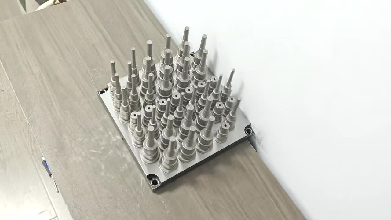
There is no single "conformal cooling" geometry for cores — the correct channel architecture depends heavily on the core's aspect ratio, diameter, and structural load requirements. Three main designs cover the vast majority of applications.
A. Helical Spiral Core
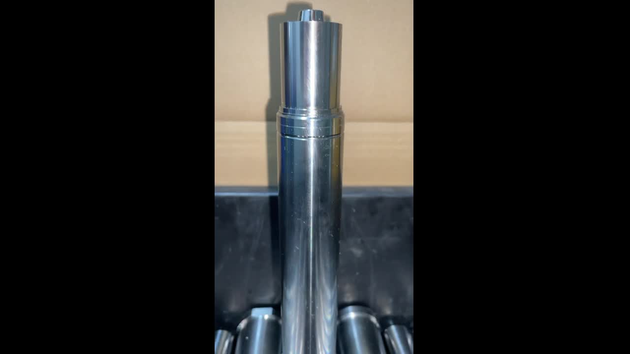
A single helical channel winds continuously from the base of the core to near the tip, then returns via a second path (or exits at the tip for inline flow). This is the most common geometry for medium-aspect-ratio cores (L/D 2–6) with OD ≥ 14mm.
- Channel cross-section: 4–6mm diameter (circular or D-profile)
- Pitch: 4–8mm per turn (tighter pitch = more cooling surface, but higher pressure drop)
- Wall thickness to core OD surface: 1.5–2.0mm
- Flow direction: Typically inlet at base, flow toward tip and return, outlet at base (U-turn at tip)
- Best for: Boss cores, ejector pin sleeves with cooling, standard round core pins
B. Double-Helix Core
Two interleaved spiral channels wrap around the core simultaneously — the inlet travels in one helix to the tip, the outlet returns via the second helix. This doubles the cooling surface area at the same pitch and eliminates the need for a U-turn feature at the tip (which is difficult to manufacture and can create stress concentrations).
- Minimum OD for double-helix: 16–18mm (to maintain wall thickness between the two channels)
- Cooling area improvement vs. single helix: Approximately 1.8× at same pitch
- Pressure drop: 30–45% lower than single helix at same flow rate (two parallel flow paths)
- Best for: Large cores ≥ 18mm OD, high-cycle molds where pressure drop budget is tight, applications requiring maximum uniformity
C. Internal Turbulator Channel
For cores in the 10–14mm OD range where a helical channel cannot be accommodated, an internal turbulator rod is inserted into a precision-drilled center bore. The turbulator creates chaotic flow (Re > 10,000 at practical flow rates) in the annular gap — dramatically improving heat transfer over a plain bubbler without requiring complex printed geometry.
- Turbulator rod diameter: 4–6mm (depends on bore diameter)
- Annular gap: 0.8–1.2mm (tight enough to force high-velocity turbulent flow)
- Heat transfer improvement vs. plain bubbler: 2.5–4× (measured Nusselt number)
- Limitations: Turbulator rod must be removable for cleaning; tip cooling is still limited vs. helical channel geometry
- Best for: Retrofit applications on existing cores, cores 10–14mm OD, round cores where LPBF printing cost is not justified
Comparison by Application
| Core L/D Ratio | Core OD | Recommended Channel Type | Tip Temp Reduction vs. Bubbler | Cycle Time Saving |
|---|---|---|---|---|
| 1–3 : 1 | ≥ 18mm | Double-helix or single helix | 20–35°C | 10–20% |
| 3–6 : 1 | 14–18mm | Single helix | 35–65°C | 20–35% |
| 5–8 : 1 | 12–14mm | Single helix (tight pitch) or turbulator | 60–90°C | 30–45% |
| 3–6 : 1 | 10–12mm | Turbulator rod | 25–45°C | 15–25% |
| Any | < 10mm | No conformal cooling — use CuCrZr core material instead | N/A | 5–15% via conductivity alone |
4. Design Rules for Conformally Cooled Cores
Designing a conformally cooled core requires balancing thermal performance, structural integrity, and manufacturability. The following rules represent the engineering constraints that cannot be violated without risking failure.
Rule 1: Minimum Wall Thickness — 1.5mm (Hard Limit)
The wall thickness between the cooling channel and the core OD surface must be at least 1.5mm for 420SS and 18Ni300 at injection pressures up to 1,200 bar. This is the absolute minimum — below this threshold, cyclic plastic pressure combined with thermal expansion fatigue will crack the wall within 50,000–200,000 shots. The practical recommended wall thickness is 2.0mm for most applications, with 1.5mm reserved for CuCrZr (which has lower structural requirements due to the lower-load applications where it's used).
Rule 2: Maximum Core Diameter That Allows Channels
For a single helical channel with 4mm diameter and 2.0mm wall thickness on each side:
- Minimum core OD = channel diameter + (2 × wall thickness on plastic side) + (2 × channel-to-center clearance) = 4 + 4 + ~4mm = ~12mm minimum OD
- Practical comfortable OD for single helix: 14mm+
- For double-helix with two 4mm channels and 1.5mm inter-channel wall: minimum 18mm OD
There is no maximum core diameter for conformal cooling — larger cores can always accommodate larger or more numerous channels for even better performance.
Rule 3: Inlet and Outlet Port Positions
Inlet and outlet connections must be located at the base of the core (the mounting flange end), not at the tip. This is mandatory for three reasons:
- The tip area has the thinnest wall and the highest structural stress — any port fitting here creates a stress concentration at the worst possible location.
- Plumbing connections at the base can be made with standard O-ring face seal fittings machined into the core retaining plate.
- Inline (series) flow from base to tip and back to base maximizes temperature differential across the core — coolant is coldest when it first contacts the hottest region near the tip.
Port diameter: 6–8mm BSP or NPT thread, or O-ring groove for push-in fittings. Always specify port location relative to orientation features (flats, keyways) on the core shank.
Rule 4: Blind End Design at the Tip
The U-turn at the core tip (where flow reverses direction from inward to outward helix) is a critical design feature. Poor blind end design causes:
- Flow dead zones — stagnant coolant at the tip creates a thermal insulating pocket precisely where you most need cooling
- Pressure concentration — abrupt U-turns create stress risers in the already thin-walled tip region
- Deposition fouling — sediment and scale accumulate in tight U-turns and cannot be purged
Best practice: design a smooth hemispherical plenum at the tip connecting the inward and outward channels. Minimum plenum volume: 1.5× the channel cross-section area. The hemispherical shape distributes stress uniformly and maintains flow velocity through the turn.
Rule 5: Core Tip Land Area
The closed tip of the core (the surface that contacts or nearly contacts the opposite cavity wall) must maintain sufficient metal thickness even after the internal plenum is incorporated. Minimum tip land thickness: 2.0mm for 420SS/18Ni300, 1.5mm for CuCrZr. Below these values, tip deflection under injection pressure leads to flash at the boss tip or premature tip cracking.
5. Material Selection
The three LPBF-printable materials used for conformally cooled mold components each offer a distinct combination of strength, hardness, and thermal conductivity. For core applications, the trade-off calculus is somewhat different than for flat inserts — cores see higher localized thermal loads but somewhat lower structural loads than cavity inserts that form large flat surfaces under full injection pressure.
| Material | Hardness (Post-HT) | Thermal Conductivity | Yield Strength | Recommended Core Application |
|---|---|---|---|---|
| 420 Stainless Steel | 48–52 HRC | 24–28 W/m·K | 1,200–1,400 MPa | General purpose: PP, PE, ABS, PS resins at ≤1,200 bar. Best cost/performance ratio. First choice for most boss and rib core applications. |
| 18Ni300 Maraging Steel | 52–56 HRC | 25–30 W/m·K | 1,900–2,100 MPa | High injection pressure (>1,200 bar), engineering resins (PC, PA-GF, POM), high-aspect-ratio cores (L/D > 6) where bending load is high, molds with >1M shots/year. |
| CuCrZr Copper Alloy | 85–95 HRB (~18–22 HRC) | 300–320 W/m·K | 400–500 MPa | Maximum heat extraction for fast-cycling, lower-pressure applications. Cores that form boss interiors in commodity resins (PP, PE) at ≤800 bar. Especially valuable for cores < 12mm OD where conformal channels cannot fit — CuCrZr's conductivity compensates for the absence of channels. |
Why CuCrZr Is More Viable for Cores Than for Flat Inserts
This is a critical distinction that many mold designers miss. CuCrZr has relatively low hardness (~18–22 HRC after aging) — which makes it unsuitable for flat cavity inserts that resist the full projected area force of injection pressure across a large surface. A 100×100mm flat insert under 1,400 bar injection pressure experiences 140 tonnes of compressive load; CuCrZr will plastically deform under this load.
A core pin is different. The dominant loading on a core pin is bending (transverse load from injection pressure asymmetry during fill) and thermal cyclic stress — not compressive load on a flat face. For a 14mm boss core forming a 14mm-diameter boss, the projected area is only 1.5cm² and the load is around 2.1 tonnes — well within CuCrZr's capabilities. The dramatically higher thermal conductivity (300 W/m·K vs. 25 W/m·K for 420SS) means CuCrZr cores run 40–60°C cooler at the tip even without conformal channels, simply by conducting heat to the base faster.
6. Core Size Minimum Thresholds
Not every core qualifies for conformal cooling. The following table defines the threshold criteria that determine which cooling strategy applies for a given core size.
| Core OD | Conformal Cooling Option | Channel Geometry Possible | Recommended Strategy |
|---|---|---|---|
| ≥ 18mm | Full conformal cooling | Double-helix or single helix (4–6mm channel) | LPBF-printed double-helix core in 420SS or 18Ni300. Best performance, highest cost. |
| 14–18mm | Full conformal cooling | Single helix (4mm channel, 2.0mm wall) | LPBF-printed single helix in 420SS. Standard recommendation for most boss/rib cores. |
| 12–14mm | Marginal conformal cooling | Single helix possible (3.5mm channel, 1.5mm wall — requires FEA validation) | LPBF with tight-pitch single helix, or turbulator rod in drilled core. FEA mandatory before production. |
| 10–12mm | Turbulator only | No helical channel — wall too thin | Turbulator rod in precision-drilled center bore. Or switch to CuCrZr core pin (no channels needed). |
| < 10mm | No conformal cooling possible | None — any internal bore leaves insufficient wall | Switch to CuCrZr core pin material. Conductivity difference (300 vs. 25 W/m·K) achieves 5–15% cycle reduction without any channels. |
7. ROI Examples
The financial case for conformally cooled cores depends on two factors: how much the core is the cycle-time-limiting feature, and what quality costs are currently being absorbed due to inadequate core cooling.
ROI Example 1: Automotive Connector Housing (16 Boss Cores, PA66-GF30)
This is a 4-cavity family mold producing an automotive connector housing. Each cavity has four 18mm-deep boss cores at 14mm OD (L/D = 1.3:1) and four 45mm-deep rib cores at 12mm OD (L/D = 3.75:1). The rib cores are the cycle-time limiting feature.
| Parameter | Conventional Bubblers | Conformal Cooled Cores |
|---|---|---|
| Rib core tip temperature (steady state) | 108°C | 51°C |
| Cycle time (cooling phase limiting) | 32.5 seconds | 22.8 seconds |
| Cycle time reduction | — | –30% (9.7 seconds) |
| Parts per hour (4 cavities) | 443 | 632 |
| Additional parts per shift (8h) | — | +1,512 parts |
| Scrap rate (warped ribs, out-of-spec) | 3.2% | 0.4% |
| Conformal core set cost (8 rib cores × 420SS) | — | ~$6,400 total |
| Estimated payback period (at $0.08/part margin) | — | 8–12 days |
In this example, the 2.8% scrap rate reduction alone (3.2% → 0.4%) adds additional value of approximately $2,400/month at the production volume of this mold — the conformal core set pays back in under two weeks from cycle time savings alone, before accounting for quality improvement.
ROI Example 2: Consumer Appliance Housing (Deep Ribs, ABS)
An 8-cavity mold producing a mixer housing. The part has twelve 55mm-deep rib cores at 10–11mm OD — too small for helical conformal channels. The solution: switch rib cores from H13 to CuCrZr and add turbulator rods.
| Parameter | H13 Core + Bubbler | CuCrZr Core + Turbulator |
|---|---|---|
| Core tip temperature | 96°C | 62°C |
| Rib warpage (mm deviation at 50mm depth) | 0.38mm | 0.09mm |
| Cycle time | 28.0 seconds | 22.4 seconds |
| Cycle time reduction | — | –20% |
| Rejection rate (warpage OOT) | 4.8% | 0.6% |
| CuCrZr core set cost (96 cores) | — | ~$9,600 total |
| Payback period | — | 10–16 days |
Factors That Increase ROI
- High resin melt temperature (PC, PA-GF, POM) — more heat input to core, greater cooling delta
- High core aspect ratio (L/D > 4) — conventional cooling is most inadequate here
- High-cavity-count molds (8, 16, 32 cavities) — cycle saving multiplies across all cavities simultaneously
- Current scrap rate above 2% due to warpage or sink marks on boss/rib features
- 3-shift production — cycle time savings work 24/7
Not Sure Which Core Cooling Strategy Applies to Your Mold?
Send us your core drawing or a sketch with OD, depth, and resin type. We'll recommend the right solution — conformal helix, turbulator, or CuCrZr material swap — and provide an ROI estimate within 24 hours, at no charge.
View Conformal Cooling Service → WhatsApp Now8. Ordering a Conformal Cooled Core
What to Send Us
To design and quote a conformally cooled core, we need the following information. The more detail you provide, the faster and more accurate our design review:
- Core drawing or 3D model — 2D drawing (PDF or DXF) with all critical dimensions: OD, length, tip geometry, shank features, tolerance on OD (we manufacture to your mold's existing core bore tolerance)
- Resin type and melt temperature — determines channel wall thickness requirement and minimum coolant temperature specification
- Injection pressure — determines material selection (420SS vs. 18Ni300) and wall thickness safety factor
- Existing cooling method — bubbler specs if currently used (helps us estimate the baseline performance and the improvement to expect)
- Coolant connection details — how cores are connected to the mold's cooling circuit (direct pipe thread, O-ring face seal, manifold block)
- Quantity — number of identical cores (affects per-unit cost significantly above 4 pieces)
What We Deliver
- Design drawing for approval — 3D model + 2D manufacturing drawing showing channel geometry, wall thicknesses, port positions, all machined features. Returned within 24–48 hours of receiving your information.
- LPBF-printed core in specified material (420SS, 18Ni300, or CuCrZr)
- Post-print heat treatment — stress relief + age hardening to specification
- CNC finishing — all critical surfaces machined to tolerance: OD to your core bore h6/h7, tip face, shank features, O-ring grooves, port threads
- Hydrostatic pressure test at 300 bar for 5 minutes — certification document included
- Surface finishing — core OD polished to Ra ≤ 0.4μm (standard), or EDM textured to your specification
- Dimensional inspection report — CMM measurement of critical dimensions with actual vs. nominal
Lead Time
| Phase | Standard Lead Time | Rush Lead Time |
|---|---|---|
| Design review and drawing approval | 24–48 hours | Same day (additional charge) |
| LPBF printing | 2–3 business days | 1–2 business days |
| Heat treatment | 1–2 business days | 1 business day |
| CNC finishing and testing | 2–3 business days | 1–2 business days |
| Total manufacturing | 7–10 business days | 4–6 business days |
| International shipping (DHL Express) | 3–14 days depending on destination | 2–5 days (priority routing) |
Rush orders to the US and Europe (DHL Express door-to-door) typically arrive within 10–14 calendar days from order confirmation, including manufacturing. Standard orders: 14–20 calendar days.