Making molds with 3D printing is now a mainstream manufacturing option — not an experimental technology. Metal additive manufacturing has matured to the point where 3D printed tooling components are running millions of production shots in automotive, medical, consumer electronics, and packaging applications worldwide. But "3D printed molds" is not a single concept: there are four fundamentally different approaches, each suited to different volume ranges, material requirements, accuracy demands, and budgets.
This guide gives you the technical detail to evaluate which approach — or combination of approaches — fits your specific program. We cover each method's process, advantages, limitations, cost structure, and volume thresholds. The comparison tables in Section 6 let you identify the right fit at a glance. Section 12 goes deep on the highest-value application: conformal cooling channels integrated into metal LPBF mold inserts, which is where MouldNova's core capabilities lie.
1. Overview: How 3D Printing Is Used to Make Molds
The phrase "making molds with 3D printing" covers a wide spectrum. At one end you have photopolymer patterns printed on a desktop SLA machine to make a silicone mold for 50 urethane castings. At the other end you have a maraging steel injection mold insert built on an industrial LPBF machine, age-hardened to 52 HRC, EDM-finished to Ra 0.4 µm, with internal conformal cooling channels that no drill could ever reach — and designed to run 1,000,000+ injection shots over its service life.
Understanding these four approaches is the foundation of any intelligent decision about additive tooling:
- 3D printed injection mold inserts with conformal cooling — Metal LPBF (laser powder bed fusion / SLM) of maraging steel or H13, installed into a conventional mold base. Used for production injection molding with dramatically superior thermal performance. This is the highest-value application and MouldNova's primary service.
- 3D printed prototype injection molds — Direct metal or polymer printing of complete short-run cavity and core sets. Used for prototype validation and bridge tooling runs of 50 to 10,000 shots before committing to production tooling.
- 3D printed patterns for silicone / urethane casting molds — SLA, FDM, or SLS-printed masters from which room-temperature-vulcanizing (RTV) silicone molds are cast. Used for rapid production of 20–200 units in polyurethane, silicone, or epoxy casting resins.
- 3D printed sand casting molds — Binder jetting of sand creates mold cavities directly without a pattern. Used for rapid aluminum, iron, or steel castings in quantities of 1–500 parts.
The right method is determined by three variables: annual volume (shots or castings), required part material (thermoplastic, urethane, aluminum, etc.), and dimensional accuracy requirements. Read Section 6's comparison table before committing to any approach.
2. Method 1: 3D Printed Injection Mold Inserts with Conformal Cooling (Metal LPBF)
This is the most technically sophisticated and financially impactful application of additive manufacturing in mold making. A cavity or core insert is designed with internal cooling channels that follow ("conform to") the cavity surface geometry — typically running 3–6 mm from the mold surface at a uniform distance. The insert is then built layer by layer on an LPBF machine from metal powder, resulting in a solid steel component with fully enclosed internal channels that would be impossible to create by any drilling or milling process.
The insert is installed into a standard mold base (A and B plates machined conventionally) and connected to the cooling circuit. From the outside, it looks like a conventional mold insert. Inside, it has a cooling network that removes heat from the part 2 to 3 times more efficiently per unit of channel length than straight-drilled alternatives.
- Volume capacity: 500,000–5,000,000+ shots (same as conventional hardened steel tooling)
- Lead time: 7–15 business days from confirmed design to finished insert
- Cycle time reduction: 20–40% depending on part geometry and resin
- Cost: $1,500–$8,000 per insert depending on size, complexity, and material
- Accuracy: ±0.05 mm post-machining, cavity surface Ra 0.2–0.8 µm after EDM/polishing
Why Conformal Cooling Works
Conventional injection mold cooling uses straight-drilled channels — holes bored through the mold steel in straight lines, connected by cross-drilled passages and plugged at non-connecting ends. The geometry of straight-drilled channels means they cannot follow curved, complex cavity surfaces. The result is variable distance between the cooling channel and the cavity surface: close in some areas, far away in others. Where channels are distant from the cavity wall, the mold surface runs hotter. Hot spots cause longer cooling times (because the molder must wait for the hottest area to solidify), warpage (differential shrinkage between hot and cold zones), and surface defects (sink marks, gloss variation).
Conformal channels solve this by maintaining a constant distance from the cavity surface regardless of geometry. The channel follows every curve, rib, and boss of the part — something only additive manufacturing can produce. The thermal result is a mold surface that stays within ±3°C across its entire area, compared to ±15–25°C for straight-drilled cooling on complex geometries.
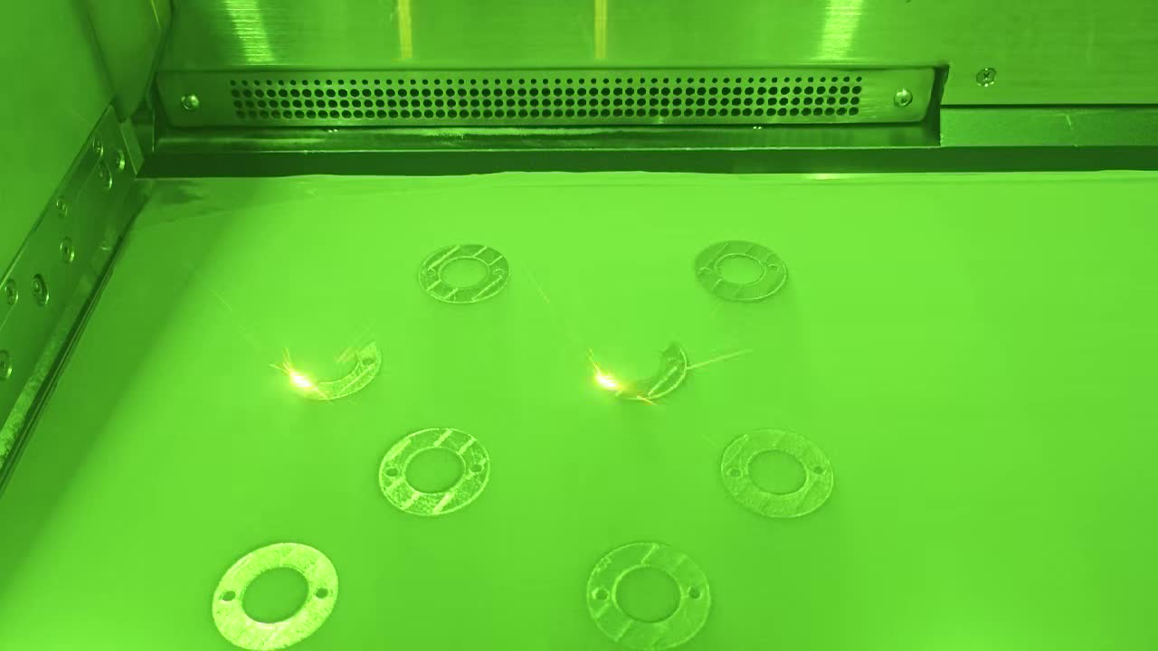
The LPBF Process for Mold Inserts
Laser powder bed fusion (LPBF) — also called SLM (selective laser melting) or DMLS (direct metal laser sintering) — is the dominant process for printing metal mold inserts. A high-power fiber laser (typically 200–1,000 W) selectively melts metal powder in a thin layer (20–60 µm), then a new powder layer is spread and the process repeats. A standard build platform of 250 × 250 mm can accommodate multiple inserts simultaneously, reducing per-insert cost at volume.
For mold inserts specifically, the LPBF process parameters are critical: energy density, scan strategy, and layer thickness determine the final material density (target: >99.5% relative density), residual stress state, and dimensional accuracy. Saiguang 3D Technology uses validated parameter sets for maraging steel MS1 and H13 that are developed specifically for mold tooling — not generic parameters adapted from other applications.
Conformal channels can spiral around a circular core, branch into multiple circuits around a complex boss, run as a saddle shape over a curved surface, or reduce in diameter as they approach the gate area. None of these geometries are achievable by drilling. This geometric freedom is the fundamental value proposition of LPBF for mold tooling — and why the technology has become standard practice in leading injection molding operations globally.
3. Method 2: 3D Printed Prototype Injection Molds for Short Runs
For short-run production or pre-production prototype validation in actual injection molding material, 3D printing complete cavity and core sets is a cost-effective alternative to conventional P20 or H13 prototype tooling. The entire mold cavity — including ejector pin holes, gate geometry, and parting line — is printed as a single component or two mating components. Because no CNC programming is required for the cavity form, lead times drop from 4–6 weeks (conventional prototype tooling) to 5–10 days.
- Volume capacity: 50–10,000 shots (material-dependent; higher with H13 vs. aluminum)
- Lead time: 5–10 business days to first shot
- Material options: AlSi10Mg (aluminum), 316L stainless, H13 tool steel
- Cost: $800–$5,000 for small to medium prototype molds (vs. $8,000–$25,000 conventional)
- Accuracy: ±0.1–0.2 mm; surface finish Ra 1.6–3.2 µm (better with post-machining)
Limitations of Direct-Printed Prototype Molds
Direct-printed prototype molds have important limitations that make them unsuitable for production use beyond approximately 10,000 shots. Aluminum inserts soften at injection temperatures for engineering resins (above 200°C), leading to cavity wear after 2,000–5,000 shots. Printed surface finish is rougher than machined and polished steel, which affects part surface quality unless post-machining is applied. Ejector systems, hot runners, and side actions must be integrated as separate machined components — the printed cavity replaces only the cavity-forming geometry, not the entire mold assembly.
For production programs, direct-printed prototype molds serve their purpose best as a bridge: fast to produce, good enough to validate part design and processing parameters in real material, and cheap enough to accept as a sunk cost when the production tool is ordered.
4. Method 3: 3D Printed Patterns for Silicone and Urethane Casting Molds
When injection molding tooling cost cannot be justified for quantities below 200–500 parts, 3D printed patterns are used to create silicone or polyurethane tooling molds. The process is simple: a master pattern of the desired part geometry is 3D printed (typically SLA or PolyJet for smooth surface finish), then RTV (room-temperature vulcanizing) silicone is poured around it and cured. When the master is removed, the silicone mold can be used to cast 20–50 urethane or epoxy parts before wear degrades dimensional accuracy.
- Volume capacity: 20–50 castings per silicone mold; 200–500 total with multiple molds from one pattern
- Lead time: 1–3 days for pattern printing; 24–48 hours for silicone curing
- Material options (cast parts): Shore A–D polyurethanes, rigid epoxy, silicone, low-melt alloys
- Cost: $50–$500 for pattern printing; $100–$400 per silicone mold
- Accuracy: ±0.2–0.5 mm; surface finish depends on master finish (SLA: Ra 0.8–1.6 µm)
The key design consideration for this method is shrinkage compensation. Silicone molds shrink 0.5–2% during curing depending on formulation, and urethane casting resins shrink an additional 0.5–1.5% as they cure and cool. Patterns must be scaled accordingly. For parts requiring close tolerances, the silicone casting route is generally limited to non-critical dimensions unless shrinkage compensation is precisely calibrated through trial casting.
5. Method 4: 3D Printed Sand Casting Molds (Binder Jetting)
Binder jetting deposits a liquid binder onto a bed of sand (silica, zircon, or chromite), selectively bonding the sand particles into a solid mold shape. The finished sand mold — cavity, core, and runner system — is then used exactly like a conventional green sand or no-bake sand mold to produce metal castings. No pattern is required: the mold geometry is built directly from the CAD file. This eliminates the pattern-making step that normally adds weeks to sand casting lead times.
- Volume capacity: Each binder jetted mold is single-use (like conventional sand molds); economics work for 1–500 castings
- Lead time: 1–3 days per mold set vs. 4–8 weeks for pattern-based sand casting
- Metal options: Aluminum alloys, gray iron, ductile iron, steel, bronze
- Cost: $200–$2,000 per mold set depending on size and complexity
- Accuracy: ±0.5–1.0 mm; surface finish Ra 6–12 µm (inherently rougher than injection molding)
6. Comparison Table: All Four Methods Side-by-Side
The following table compares all four 3D printing mold approaches across the dimensions most relevant to tooling decision-making. Use this as a rapid-selection tool before diving into method-specific detail.
| Criterion | Method 1: LPBF Conformal Inserts | Method 2: Direct Metal Prototype Mold | Method 3: Silicone Casting Pattern | Method 4: Binder Jet Sand Mold |
|---|---|---|---|---|
| Volume Range | 50,000–5M+ shots | 50–10,000 shots | 20–500 castings | 1–500 castings |
| Part Material | Any thermoplastic or thermoset | Most thermoplastics (limited high-temp) | Polyurethane, silicone, epoxy resin | Aluminum, iron, steel, bronze |
| Tool Lead Time | 7–15 days | 5–10 days | 2–5 days | 1–3 days per mold |
| Tooling Cost | $1,500–$8,000/insert | $800–$5,000/mold set | $150–$900/mold set | $200–$2,000/mold set |
| Dimensional Accuracy | ±0.05 mm (post-machined) | ±0.1–0.2 mm | ±0.2–0.5 mm | ±0.5–1.0 mm |
| Surface Finish | Ra 0.2–0.8 µm (polished) | Ra 1.6–3.2 µm | Ra 0.8–2.0 µm | Ra 6–12 µm |
| Cycle Time vs. Conventional | 20–40% faster | Similar or slower | N/A (different process) | N/A (different process) |
| Key Advantage | Conformal cooling + production tool life | Fast to first shot, low tooling cost | Very low cost, fast for <500 parts | No pattern needed, complex internal cores |
| Key Limitation | Insert cost premium over drilling | Limited tool life, rougher surface | Low volume, dimensional variation | Single-use mold, rough surface |
| MouldNova Service? | Yes — primary service | Yes | Pattern printing only | Referral to foundry partners |
Application Selection Matrix
| Your Situation | Recommended Approach |
|---|---|
| Production injection molding, >100k shots/year, cycle time is costing money | Method 1 — LPBF Conformal Cooling Inserts |
| Need to validate part design in real PP, ABS, or PA66 before production tool commitment | Method 2 — Direct Metal Prototype Mold |
| Need 50–200 functional urethane or silicone parts within 2 weeks, no injection tool budget | Method 3 — Silicone Casting from 3D Printed Pattern |
| Need 5–50 aluminum or iron castings without pattern investment, complex internal geometry | Method 4 — Binder Jet Sand Mold |
| Production injection molding, <50k shots/year, tight budget | Conventional machined tooling (3D printing premium not justified at this volume) |
| High-volume production with warpage problems on complex geometry parts | Method 1 — LPBF Conformal Cooling Inserts (even if current tooling is conventional) |
7. Materials for 3D Printed Molds
Material selection for 3D printed mold tooling is more consequential than in most other additive manufacturing applications, because mold materials are subjected to cyclic thermal stress, high injection pressures (700–2,000 bar), chemical exposure to hot molten plastic, and abrasion from filled resins. The following materials are qualified and in regular use for each application:
Maraging Steel (MS1 / 18Ni300) — Production Injection Mold Inserts
Maraging steel is the dominant material for LPBF mold inserts. In the as-printed condition, MS1 has a hardness of approximately 33–38 HRC. After age hardening (480–490°C for 6 hours), hardness increases to 50–54 HRC without the distortion risk associated with quench hardening of conventional tool steels. This makes maraging steel uniquely suited to post-print heat treatment: the insert can be printed near-net-shape, machined and polished, then age-hardened — with minimal distortion because the aging treatment operates at relatively low temperature.
Key properties for mold applications: yield strength 1,800–2,050 MPa (age-hardened), thermal conductivity 20 W/m·K, good weldability for insert repair, and excellent printability with >99.5% density achievable on qualified LPBF machines. Limitation: not suitable for injection temperatures above approximately 350°C (limits use with PEEK and high-temperature LCP).
H13 Hot-Work Tool Steel — High-Temperature Injection Mold Inserts
H13 (DIN 1.2344) is the standard material for conventional injection mold tooling worldwide, and it can also be processed by LPBF. Printed H13 achieves 50–56 HRC after vacuum heat treatment, with superior thermal fatigue resistance compared to maraging steel. This makes it the preferred choice for molds running high-temperature engineering resins (PEEK, PPS, LCP, high-melt PEI) or for molds with thin gate land areas subject to cyclic thermal shock. The challenge with LPBF H13 is that the optimal heat treatment requires vacuum quenching, adding cost and time compared to maraging steel's simple aging cycle.
Aluminum (AlSi10Mg) — Short-Run Prototype Molds
AlSi10Mg is a casting alloy that prints well by LPBF and achieves 130–170 HV after T6-equivalent heat treatment. It is widely used for short-run prototype mold inserts because of its low cost (less than half the material cost of tool steel), high thermal conductivity (100–150 W/m·K vs. 20 W/m·K for tool steel), and fast machining. Limitations: low hardness limits tool life to approximately 5,000–10,000 shots with most amorphous thermoplastics; unsuitable for glass or mineral filled resins; not suitable for temperatures above 200°C.
Photopolymer Resins — SLA Casting Patterns
For Method 3 (silicone casting patterns), high-accuracy SLA resins — particularly rigid engineering resins with HDT (heat deflection temperature) above 80°C — are standard. The key requirement is that the pattern survive the RTV silicone curing process (typically 24 hours at room temperature to 60°C) without distortion. Standard SLA rigid resin is adequate for room-temperature curing silicone. For elevated-temperature silicone curing cycles, engineering resins with HDT >200°C are required.
Silica / Zircon Sand — Binder Jetting Molds
For Method 4 (sand casting molds), binder jet sand systems use silica sand (for iron and steel casting) or zircon sand (for aluminum, where finer grain size improves surface finish). The binder is typically an inorganic or furan-based system. Finished sand molds have a green strength of 0.5–2.0 MPa before curing, and final strength of 3–8 MPa after thermal or chemical curing — adequate for the pressures of gravity-poured or low-pressure aluminum casting.
8. Design Considerations for 3D Printed Mold Tooling
3D printed mold tooling requires the same fundamental design practices as conventional injection mold tooling — plus specific considerations driven by the additive manufacturing process. Failing to account for these in the design phase leads to printed parts that require extensive rework or fail in service.
Draft Angles
Draft angles for 3D printed injection mold inserts follow the same rules as conventional tooling: minimum 0.5° per side for cosmetic surfaces, 1–2° for textured surfaces, and 3–5° for deep ribbed structures. The additive process does not change part ejection physics. A common error when first transitioning to 3D printed inserts is assuming that printed surface texture eliminates the need for draft — it does not. Insufficient draft on a printed cavity (which may have slightly higher Ra than a polished conventional cavity) increases ejection force and accelerates insert wear at ejection contact points.
Parting Lines
Parting lines for 3D printed inserts must be designed with the same care as conventional tooling. The LPBF process can print complex parting surfaces, including stepped, angled, or contoured parting lines, but these surfaces require post-machining to achieve the metal-to-metal fit quality needed to prevent flash. Budget EDM finish machining time for all parting surface features when quoting 3D printed insert programs.
Conformal Cooling Channel Design Rules
For Method 1 inserts with conformal cooling, channel design follows established guidelines derived from both thermal simulation and printability constraints:
- Channel-to-surface distance: 3–6 mm from cavity wall (closer increases thermal efficiency but reduces structural strength of the insert wall between channel and cavity)
- Channel diameter: 6–12 mm internal diameter is optimal for heat transfer and printability; channels narrower than 4 mm are prone to powder sintering in unsupported horizontal sections and difficult to clean
- Channel-to-channel pitch: 2–3× channel diameter (e.g., 15–20 mm center-to-center for an 8 mm channel)
- Minimum wall thickness between channels: 4 mm for maraging steel, 5 mm for H13, to maintain structural integrity under injection pressure
- Build orientation: Channels should be oriented at 45° or greater from horizontal to avoid unsupported overhanging channel walls — channels printed vertically or at steep angles have better internal surface quality and require less support removal
- Inlet / outlet connectivity: Channel networks must connect to the mold's standard cooling circuit; interface fittings (typically BSP 1/8" or NPT 1/8") are post-machined into the insert after printing
Surface Finish Planning
As-printed LPBF steel surfaces have Ra of 6–15 µm — too rough for injection molding cavity surfaces. All cavity-forming surfaces require post-processing. Plan the following finish allowances in the CAD model:
- CNC milling finish: +0.3–0.5 mm stock on flat and contoured surfaces
- EDM finish: +0.1–0.2 mm stock for fine features and ribs
- Polishing: no additional stock, but budget 4–20 hours of manual polishing per insert for mirror or high-gloss applications
9. Post-Processing Requirements
Post-processing is a mandatory and significant cost component for any 3D printed mold insert. Unlike general industrial LPBF parts where as-built surface finish may be acceptable, injection mold inserts require a defined sequence of post-processing operations before they can run production shots.
As-printed LPBF steel parts contain residual stress from the rapid heating and cooling of the laser melting process. Before removing the insert from the build plate, a stress relief cycle (typically 450°C for 4 hours under protective atmosphere) reduces distortion risk during removal. Wire EDM is then used to cut the insert free from the build plate with minimal induced stress.
External support structures are removed by milling, grinding, or hand tools. Internal cooling channels are flushed with compressed air and abrasive flow media to remove any sintered powder that adhered to channel walls during printing. Channel cleanliness is critical: even small amounts of trapped powder will restrict flow and cause localized hot spots that defeat the purpose of conformal cooling.
All reference surfaces (insert seating surfaces, parting line, ejector pin holes) are finish-machined by CNC to achieve the dimensional accuracy and surface quality required for mold assembly. This step brings overall dimensional accuracy from ±0.1–0.2 mm (as-built LPBF) to ±0.02–0.05 mm (post-machined). EDM is used for fine features including sharp corners, narrow ribs below 1 mm, and gate inserts.
Maraging steel inserts are age-hardened at 480–490°C for 5–6 hours, increasing hardness from 33–38 HRC (as-built) to 50–54 HRC. Because the aging treatment involves no quenching, distortion is minimal — typically less than 0.02 mm on a 100 mm insert. H13 inserts require vacuum austenitizing (1,020–1,050°C), quench, and double temper — a more involved cycle that is performed by a certified heat treatment house.
Cavity surfaces are polished to the required finish (from Ra 0.8 µm for standard applications to Ra <0.05 µm for optical or medical parts). Cooling channels are pressure-tested at 1.5× operating pressure (typically 15–25 bar test pressure) to verify channel integrity before the insert is installed in the mold. Any leak at a channel wall indicates a print defect that requires repair or insert replacement before production use.
10. Volume Thresholds: When 3D Printing Makes Sense vs. Conventional
The most common question about making molds with 3D printing is the break-even volume question: at what production quantity does the additive approach pay for itself versus conventional machining? The answer depends heavily on which method and which metric you are optimizing.
For Conformal Cooling Inserts (Method 1)
The economic comparison for conformal cooling inserts is not simply "insert cost vs. conventional drill cost" — it is "insert cost premium vs. savings from cycle time reduction and quality improvement over the tool's life." A typical conformal cooling insert in maraging steel costs $2,000–$4,000 more than a conventionally drilled insert of the same size. But the cycle time savings of 25–35% on a tool running 500,000 shots/year at $80/hr machine rate generates $30,000–$60,000 in annual throughput savings — making the payback period measured in days, not years.
For Direct Metal Prototype Molds (Method 2)
The comparison here is against conventional prototype tooling: machined P20 or hardened H13 prototype inserts, which typically cost $8,000–$25,000 and take 4–6 weeks. A 3D printed aluminum prototype mold for the same part costs $800–$3,000 and arrives in 5–10 days. The trade-off is tool life (5,000 shots vs. 50,000+ shots for machined H13) and surface quality (rougher unless post-machined). For programs where the prototype mold will run 500–5,000 validation shots before a production tool is ordered, 3D printing is almost always the better economic choice.
For Silicone Casting Patterns (Method 3)
The economics are simple: below approximately 200 units, the total cost of a 3D printed pattern plus silicone molds plus urethane casting is almost always lower than the minimum injection mold cost (typically $5,000–$15,000 for a simple prototype injection tool). Above 500 units, injection molding becomes competitive on a per-part basis even accounting for tooling cost amortization.
11. Cost Analysis
The following cost ranges reflect real 2025–2026 market pricing for each 3D printed mold approach, including post-processing and finishing to injection-ready condition. Significant variation exists based on insert size, complexity, and required surface finish:
| Cost Component | LPBF Conformal Insert (100×100×80 mm) | Al Prototype Mold (2-cavity, simple part) | Silicone Pattern + Mold (SLA + 2 molds) |
|---|---|---|---|
| 3D Printing / Fabrication | $1,200–$2,400 | $400–$900 | $80–$300 |
| Material (Powder / Resin) | Included above | Included above | $50–$200 |
| Post-Machining (CNC + EDM) | $600–$1,800 | $200–$800 | N/A |
| Heat Treatment | $200–$400 | $80–$200 (T6) | N/A |
| Polishing / Texturing | $300–$1,200 | $100–$400 | N/A |
| Pressure Testing + QC | $100–$200 | N/A | N/A |
| Total Range | $2,400–$6,000 | $780–$2,300 | $130–$700 |
| Equivalent Conventional Cost | $900–$2,500 (drilled insert) | $8,000–$25,000 (machined P20 prototype) | $5,000–$15,000 (injection prototype tool) |
| 3D Printing Premium / Saving | +$1,500–$3,500 premium | 70–90% cost saving | 95%+ cost saving |
The conformal cooling insert premium of $1,500–$3,500 is not a cost — it is an investment with a typical payback period of 3–15 production days at typical automotive or consumer goods injection molding volumes. The premium disappears in throughput savings within the first month of production in virtually all programs above 200,000 annual shots.
12. How Conformal Cooling Integrates into 3D Printed Mold Inserts
Conformal cooling is the feature that transforms an ordinary metal LPBF mold insert into a high-performance production tooling component. Understanding how the integration works — from design through testing — helps tooling engineers specify and evaluate conformal cooling insert programs more accurately.
Step 1: Thermal Simulation Before Design Finalization
Before any cooling channel geometry is committed to CAD, MouldNova runs a Moldflow Cooling (MCC) simulation of the conventional cooling scenario for comparison. This simulation identifies: (a) peak surface temperature locations (hot spots), (b) temperature gradient across the cavity surface at end of cooling phase, (c) minimum cycle time achievable with conventional cooling, and (d) warpage map showing which features will deform due to differential cooling. This baseline defines exactly where conformal channels need to be routed and how close they need to run to the cavity surface to achieve the target temperature uniformity.
Step 2: Channel Network Design in CAD
The conformal channel network is designed as a series of sweeping channel paths following the cavity surface geometry. The design observes all printability rules: channel angle relative to build direction, minimum wall thickness between adjacent channels and between channels and the cavity surface, inlet/outlet placement for connectivity to mold cooling circuit manifolds, and turbulence promoter features (slight spiraling or baffling) to maximize heat transfer at a given flow rate.
After initial channel layout, a second Moldflow simulation validates the design against the temperature uniformity and cycle time targets. Channels are adjusted iteratively until simulation confirms the target is met — typically within 2 simulation cycles for experienced conformal cooling designers.
Step 3: Build Orientation and Support Strategy
The insert is oriented on the build plate to minimize support structures inside cooling channels (which are difficult to remove) and to maximize the mechanical properties in the loading direction (typically oriented so the build layers are perpendicular to the primary injection force direction). Support structures on external non-functional surfaces are acceptable and easily removed; support inside channels must be avoided by channel angle management.
Step 4: Post-Processing and Integration
After printing and heat treatment, the insert's cooling circuit connection points (inlet and outlet ports) are finish-machined with threads or O-ring grooves to accept standard fittings. The channels are flushed, pressure-tested, and then the insert is dimensionally inspected before installation in the mold base. Installation of a conformal cooling insert into an existing mold base requires only that the insert's external dimensions match the pocket in the mold plate — the internal cooling circuit is entirely self-contained within the insert.
See MouldNova's 3D Printed Mold Inserts service page and Conformal Cooling Inserts service page for complete technical specifications, material options, and lead time details. Our Rapid Tooling Service covers programs requiring fast-turn complete tooling solutions.
13. Real Application Examples
Part: ABS medical device housing, 95 × 60 × 35 mm, wall thickness 2.0–3.5 mm, two deep boss features 28 mm tall.
Problem: Conventional baffle cooling in the boss cores could not maintain adequate cooling at the base of the 28 mm bosses. Cooling time extended to 22 seconds to achieve acceptable part temperature, and warpage at the boss base was 0.35 mm — exceeding the 0.20 mm assembly tolerance.
Solution: LPBF maraging steel inserts with helical conformal cooling channels running at 4 mm from the boss core surface, including a spiraling channel inside the boss core itself. Cycle time reduced to 14 seconds. Warpage at boss base: 0.08 mm.
Result: 36% cycle time reduction, warpage within tolerance, $87,000/year throughput saving at 400,000 shots/year program volume. Insert payback: 11 days.
Part: PC/ABS smartphone protective case, thin-wall geometry (1.2 mm nominal), snap-feature detail requiring accurate core geometry.
Problem: Product design team needed 500 pre-production samples in actual PC/ABS to test drop resistance and fit before committing to a $35,000 production tool. Conventional prototype tooling would cost $12,000 and take 5 weeks — too slow for the product launch schedule.
Solution: 3D printed aluminum (AlSi10Mg) 2-cavity prototype mold, post-machined at parting line and cavity walls, delivered in 8 business days. Total cost: $2,200.
Result: 500 parts produced in actual PC/ABS material for drop testing and fit validation. Product design confirmed before production tool order. Cost saving vs. conventional prototype tool: $9,800.
Part: Custom polyurethane gasket / seal for industrial enclosure, Shore 60A, 200 × 80 × 12 mm, 150 units required per year.
Problem: Injection molded silicone tooling cost ($8,000–$12,000) was not justifiable at 150 units/year. Lead time for conventional tooling (8 weeks) also exceeded program schedule.
Solution: SLA-printed rigid urethane master pattern, two RTV silicone molds cast from the master, producing 30–40 castings per mold. Total tooling cost: $480. Lead time: 4 days to first part.
Result: 150 units/year produced at $18/part casting cost (vs. estimated $6/part injection molding cost but with $11,000 tooling sunk cost). Net annual cost lower than injection molding until approximately 1,800 units/year volume.
Part: Aluminum die-cast structural bracket, 180 × 90 × 55 mm, complex internal ribbing, 5 units needed for engineering validation testing.
Problem: Die casting tool cost ($40,000+) and 12-week lead time were unacceptable for engineering validation of a part not yet confirmed for production. Sand casting with conventional pattern would cost $8,000 and take 6 weeks due to pattern machining.
Solution: Binder jetted sand molds (cavity + cores) produced from CAD in 2 days. Aluminum A380 gravity-poured in foundry partner's facility. 5 castings delivered for machining and testing in 8 total working days.
Result: Engineering validation testing completed 10 weeks ahead of conventional pattern-based sand casting schedule. Tooling cost: $1,200 for sand molds. Parts required minor machining to achieve final dimensions.
14. FAQ — Making Molds with 3D Printing
Yes — metal LPBF (laser powder bed fusion) produces injection mold inserts from maraging steel or H13 tool steel that are production-grade tooling components capable of running 500,000 to 5,000,000+ injection shots over their service life. These inserts are not experimental: they are standard practice in automotive, medical, consumer electronics, and packaging injection molding operations worldwide. The printed insert is finished by CNC machining, EDM, heat treatment, and polishing before installation, making it functionally equivalent to a conventionally machined insert — with the addition of internal conformal cooling channels that no drill can produce.
A 3D printed mold insert is a single cavity or core component built by metal 3D printing and then installed into a conventionally machined mold base. Only the cavity-forming inserts are 3D printed; the A and B plates, ejector system, hot runner, and side actions are machined conventionally. This hybrid approach maximizes the benefit of 3D printing (complex internal cooling geometry and cavity features) while keeping simpler structural components in conventionally machined steel. A "3D printed mold" in the broadest sense refers to printing the complete tool, which is primarily used for prototype molds and very short runs where speed matters more than tool life.
Maraging steel (MS1 / 18Ni300) is the preferred material for production conformal cooling inserts: it achieves 50–54 HRC after age hardening, prints with low residual stress, and is easily weldable for repair. H13 hot-work tool steel is used when high thermal fatigue resistance is required (high-temperature engineering resins above 300°C injection temperature). AlSi10Mg aluminum alloy is used for short-run prototype molds (under 10,000 shots) due to lower cost and high thermal conductivity. SLA photopolymer resins are limited to casting patterns — not suitable for direct injection molding except for extremely low-pressure, low-shot prototype trials with non-filled amorphous resins.
Conformal cooling channels are designed as hollow passages running through the interior of the printed steel insert, following the contour of the cavity surface at a uniform distance (typically 3–6 mm). Because LPBF builds the insert layer by layer, these channels can spiral, branch, and follow any geometry — something physically impossible to drill. After printing and heat treatment, the channels connect to the mold's standard cooling circuit via machined fittings. The thermal result is cavity surface temperature uniformity within ±3°C across the entire mold face (vs. ±15–25°C for straight-drilled cooling on complex geometry), which translates to 20–40% cycle time reduction and dramatic warpage improvement.
For conformal cooling inserts, the economics are compelling at any volume above approximately 50,000 annual shots. The insert cost premium over conventional drilling ($1,500–$3,500 for a typical insert) is recovered within 20,000–50,000 shots through cycle time savings — measured in days, not months, at automotive or consumer goods volumes. For direct-printed prototype molds (Method 2), the economics work best below 10,000 shots, where 3D printing tooling cost is 70–90% lower than conventional prototype tooling. For volumes between 50,000 and 200,000 shots/year where warpage is not a problem and cycle time is adequate with conventional cooling, conventional machined tooling often remains the right choice — 3D printing is not universally superior at every volume point.
Related Pages and Articles
- 3D Printed Mold Inserts — Service Details, Materials & Specifications
- Metal 3D Printing Service — LPBF Capabilities in Maraging Steel, H13, and Aluminum
- Rapid Tooling Service — Fast-Turn Complete Tooling Solutions
- Conformal Cooling Inserts — Full Technical Specifications
- Conformal Cooling Benefits — Five Benefit Categories with a 3-Year Factory Model
- Conformal Cooling ROI: Payback Period, Annual Savings & 5-Year NPV Calculator
- Conformal Cooling for Automotive Injection Molding: Interior Trim, Connectors & Under-Hood Parts
- Case Studies — Full Production Data from Real Programs